A861E AUTOMATIC TRANSMISSION / TRANSAXLE FLOOR SHIFT ASSEMBLY REASSEMBLY
PROCEDURE

 1.APPLY GREASE
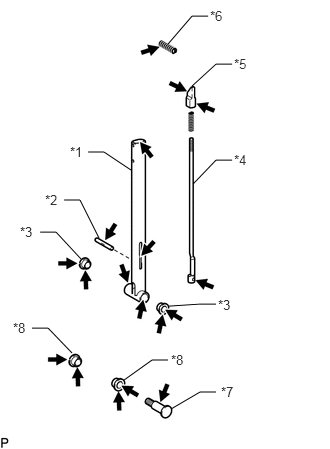
| *1 | Floor Shift Shift Lever Sub-assembly |
| *2 | Detent Rod Grooved Pin |
| *3 | Shift Lever Bush |
| *4 | Detent Rod |
| *5 | Shift Lever Knob Sleeve |
| *6 | Shift Lever Knob Button Compression Spring |
| *7 | Floor Shift Control Link Shaft |
| *8 | Control Shaft Bush |
Apply MP grease to the sliding parts of the floor shift shift lever sub-assembly, detent rod grooved pin, shift lever bush, detent rod, shift lever knob sleeve, shift lever knob button compression spring, floor shift control link shaft and control shaft bush.
33631
2.INSTALL DETENT ROD
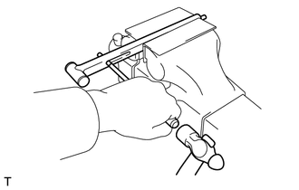
Hold the floor shift shift lever sub-assembly in a vise between aluminum plates.
- NOTICE:
-
Do not overtighten the vise.
Install the detent rod and No. 1 shift lever wire guide to the floor shift shift lever sub-assembly.
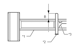
| *1 | Floor Shift Shift Lever Sub-assembly |
| *2 | Detent Rod Grooved Pin |
| *3 | Detent Rod |
Using a pin punch, tap in the detent rod grooved pin to dimension B, which was measured before tapping out the detent rod grooved pin.
33625
3.INSTALL SHIFT LEVER KNOB SLEEVE
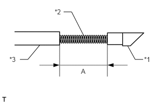
| *1 | Shift Lever Knob Sleeve |
| *2 | Detent Rod Compression Spring |
| *3 | Floor Shift Shift Lever Sub-assembly |
Install the detent rod compression spring to the floor shift shift lever sub-assembly.
Screw in the shift lever knob sleeve to dimension A, which was measured before removing the shift lever knob sleeve.
85933
4.INSTALL SHIFT LOCK CONTROL ECU
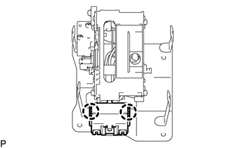
Attach the 2 claws to install the shift lock control ECU to the shift lever plate.
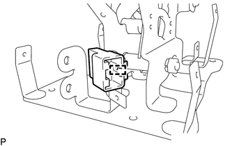
Attach the clamp to connect the shift lock control ECU connector to the shift lever plate.
33503F
5.INSTALL FLOOR SHIFT SHIFT LEVER SUB-ASSEMBLY
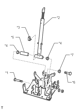
| *1 | Floor Shift Control Shaft |
| *2 | Floor Shift Shift Lever Sub-assembly |
| *3 | No. 2 Shift Lever Wire Guide |
| *4 | Shift Lever Bush |
| *5 | Shift Lever Collar |
| *6 | Floor Shift Control Link Shaft |
| *7 | Control Shaft Bush |
Install the floor shift control link shaft and control shaft bush to the shift lever plate.
Install the No. 2 shift lever wire guide and 2 shift lever bushes, shift lever collar to the floor shift shift lever sub-assembly.
Install the floor shift control shaft and floor shift shift lever sub-assembly to the shift lever plate with the nut and washer.
- Torque:
- 12.7 N*m (130 kgf*cm, 9 ft.*lbf)
33054
6.INSTALL NO. 2 FLOOR SHIFT LEVER SUB-ASSEMBLY
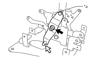
| *a | Pin |

|
MP grease |
Insert the pin of the No. 2 floor shift lever sub-assembly into the groove of the floor shift shift lever sub-assembly and install the No. 2 floor shift lever sub-assembly to the shift lever plate with the washer, control shaft bush and nut.
- Torque:
- 12.7 N*m (130 kgf*cm, 9 ft.*lbf)
Apply MP grease to the No. 2 floor shift lever sub-assembly.
84727
7.INSTALL SHIFT LOCK CONTROL SWITCH
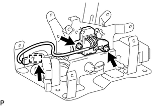
Install the shift lock control switch to the shift lever plate with the 2 screws.
Attach the clamp to connect the shift lock control switch connector to the shift lever plate.
Connect the shift lock control ECU connector to the shift lock control switch connector.
33058
8.INSTALL SHIFT LOCK SOLENOID BRACKET SUB-ASSEMBLY
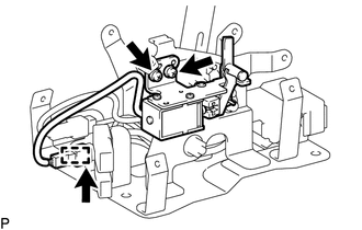
Install the shift lock solenoid bracket sub-assembly to the shift lever plate with the 2 screws.
Attach the clamp to connect the shift lock solenoid connector to the shift lever plate.
Connect the shift lock control ECU connector to the shift lock solenoid connector.
35974
9.INSTALL LOWER POSITION INDICATOR HOUSING
Install the bulb to the indicator light wire.
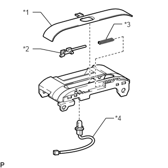
| *1 | Position Indicator Slide Cover |
| *2 | Shift Lock Release Link |
| *3 | Shift Lock Release Link Compression Spring |
| *4 | Indicator Light Wire |
Install the position indicator slide cover and shift lock release link, shift lock release link compression spring, indicator light wire to the lower position indicator housing.
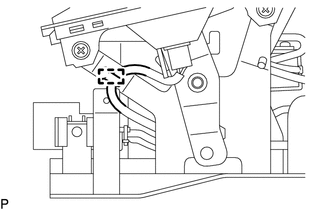
Attach the clamp to connect the indicator light wire.
Attach the 8 clamps to install the upper position indicator housing to the lower position indicator housing.
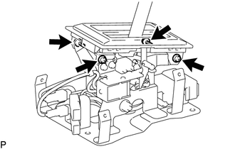
Install the lower position indicator housing to the shift lever plate with the 4 screws.
Install the shift lock release button cover.
84722
10.INSTALL TRANSMISSION CONTROL SWITCH
Install the transmission control switch to the shift lever knob sub-assembly.
33504F
11.INSTALL SHIFT LEVER KNOB SUB-ASSEMBLY
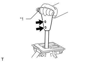
| *1 | Shift Lever Knob Button |
Install the shift lever knob button and shift lever knob button compression spring to the shift lever knob sub-assembly.
Pass the transmission control switch wire between the floor shift shift lever sub-assembly and shift lever wire guide, and then while pressing the shift lever knob button by hand, install the shift lever knob sub-assembly to the floor shift shift lever sub-assembly with the 2 screws.
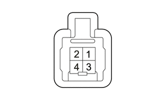
Connect the 2 and 4 terminals to the transmission control switch connector.
- NOTICE:
-
Make sure to install each terminal in the correct position.
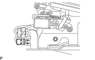
Connect the transmission control switch connector to the shift lever plate.
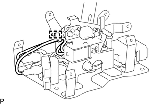
Attach the clamp to connect the wire harness.