ENGINE HOOD / DOOR AUTOMATIC DOOR SYSTEM(for Glide Type) TERMINALS OF ECU
CHECK AUTOMATIC DOOR CONTROL RELAY ASSEMBLY
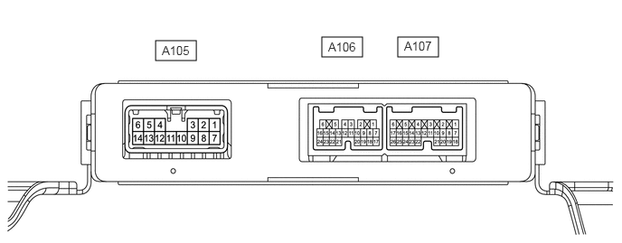
Disconnect the A106, A107 and A105 automatic door control relay assembly connectors.
Measure the voltage and resistance according to the value(s) in the table below.
| Tester Connection | Wiring Color | Terminal Description | Condition | Specified Condition |
|---|---|---|---|---|
|
*: for N04C-UH or N04C-WA |
||||
| A105-1 (B) - Body ground | B - Body ground | Power supply | Always | 11 to 14 V |
| A105-2 (GND) - Body ground | W-B - Body ground | Ground | Always | Below 1 Ω |
| A105-7 (B) - Body ground | B - Body ground | Power supply | Always | 11 to 14 V |
| A105-8 (GND) - Body ground | W-B - Body ground | Ground | Always | Below 1 Ω |
| A106-6 (SGND) - Body ground | W-B - Body ground | Ground | Always | Below 1 Ω |
| A106-7 (GND) - Body ground* | W-B - Body ground | Ground | Always | Below 1 Ω |
| A107-1 (B) - Body ground | V - Body ground | Power supply | Always | 11 to 14 V |
| A107-2 (IG) - Body ground | G - Body ground | Power supply | Ignition switch off → ignition switch ON | Below 1 V → 11 to 14 V |
| A107-4 (SGND) - Body ground | W-B - Body ground | Ground | Always | Below 1 Ω |
Reconnect the A106, A107 and A105 automatic door control relay assembly connectors.
Measure the voltage and waveform according to the value(s) in the table below.
| Tester Connection | Wiring Color | Terminal Description | Condition | Specified Condition |
|---|---|---|---|---|
|
*1: for LHD *2: for RHD *3: w/ Door Control Switch Assembly |
||||
| A105-3 (UL-) - A105-2 (GND1) | W - W-B | Automatic door regulator motor drive output signal (close operation) | Center door close operation → closer operation → center doorfully closed | Pulse generation
(See waveform 1) |
| A105-4 (UL1) - A105-2 (GND1) | R - W-B | Release motor drive signal | Center door fully closed → center door open operation | Pulse generation
(See waveform 2) |
| A105-14 (UL2) - A105-2 (GND1) | L - W-B | Release motor drive signal | Center door fully closed → center door open operation | Pulse generation
(See waveform 3) |
| A105-9 (UL+) - A105-2 (GND1) | B - W-B | Automatic door regulator motor drive output signal (open operation) | Center door close operation → closer operation → center door fully closed | Pulse generation
(See waveform 4) |
| A105-11 (UL) - A105-10 (E) | R - L | Magnetic clutch drive signal | Magnetic clutch is engaged | Pulse generation
(See waveform 5) |
| A105-12 (DC+) - A105-2 (GND1) | B - W-B | Rear closer motor drive signal | Center door close operation → closer operation → center door fully closed | Pulse generation
(See waveform 6) |
| A105-13 (DC-) - A105-2 (GND1) | L - W-B | Rear closer motor drive signal | Center door close operation → closer operation → center door fully closed | Pulse generation
(See waveform 7) |
| A106-2 (DC+) - A106-6 (SGND) | L - W-B | Front closer motor drive signal | Center door close operation → closer operation → center door fully closed | Pulse generation
(See waveform 8) |
| A106-5 (DC-) - A106-6 (SGND) | V - W-B | Front closer motor drive signal | Center door close operation → closer operation → center door fully closed | Pulse generation
(See waveform 8) |
| A106-9 (MSW) - A106-6 (SGND) | LG - W-B | Power slide door main switch signal | Power slide door main switch not pressed → power slide door main switch pressed | 11 to 14 V → Below 1 V |
| A106-11 (LMT) - A106-6 (SGND) | V - W-B | Front initial position switch input | Center door close operation → closer operation → center door fully closed | Pulse generation
(See waveform 9) |
| A107-7 (BZR+) - A106-6 (SGND) | G - W-B | Buzzer drive signal output | Buzzer does not sound → buzzer sounds | 11 to 14 V → Below 1 V |
| A106-17 (FUL) - A106-6 (SGND) | P - W-B | Rear full-latch switch input | Center door close operation → closer operation → center door fully closed | Pulse generation
(See waveform 10) |
| A106-19 (POL) - A106-6 (SGND) | W - W-B | Front pawl switch input | Center door close operation → closer operation → center door fully closed | Pulse generation
(See waveform 11) |
| A106-20 (HAF) - A106-6 (SGND) | B - W-B | Front half-latch switch input | Center door close operation → closer operation → center door fully closed | Pulse generation
(See waveform 10) |
| A106-23 (LSWD) - A106-6 (SGND) | R - W-B | Front initial position switch input | Center door close operation → closer operation → center door fully closed | Pulse generation
(See waveform 12) |
| A107-3 (ER) - A107-4 (SGND) | P - W-B | Power source of pulse sensor | Always | 11 to 14 V |
| A107-11 (FLOP) - A107-4 (SGND) | V - W-B | Full-open switch input | Center door fully open → center door not fully open | Below 1 V → 11 to 14 V |
| A107-14 (HSW) - A107-4 (SGND) | R - W-B | Glide door lock remote control assembly operation signal | Glide door lock remote control assembly not operated → glide door lock remote control assembly operated | 11 to 14 V → Below 1 V |
| A107-15 (SOUT) - A107-4 (SGND)*3 | V - W-B | Door control switch assembly signal | Door control switch assembly not push → door control switch assembly push | 11 to 14 V → Below 1 V |
| A107-16 (P/W) - A107-4 (SGND) | W - W-B | Neutral switch signal input | Center door fully closed → center door open operation | Pulse generation
(See waveform 9) |
| A107-17 (SIG) - A107-4 (SGND) | B - W-B | Full switch signal input | Center door fully closed → center door open operation | Pulse generation
(See waveform 13) |
| A107-20 (L+) - A107-4 (SGND) | P - W-B | Front full-latch switch input | Center door close operation → closer operation → center door fully closed | Pulse generation
(See waveform 11) |
| A107-21 (TRLY) - A107-4 (SGND) | L - W-B*1
LG - W-B*2 |
AUTO DR relay drive signal output | Ignition switch off → ignition switch ON | Below 1 V → 11 to 14 V |
| A107-24 (HAF) - A107-4 (SGND) | P - W-B | Rear half-latch switch input | Center door close operation → closer operation → center door fully closed | Pulse generation
(See waveform 10) |
| A107-25 (SPD) - A107-4 (SGND) | V - W-B | Vehicle speed signal | Vehicle being driven atapproximately 5 km/h (3mph) | Pulse generation
(See waveform 14) |
| A107-26 (SW) - A107-4 (SGND) | W - W-B | Front pawl switch input | Center door close operation → closer operation → center door fully closed | Pulse generation
(See waveform 15) |
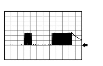
Using an oscilloscope, check waveform 1.
- NOTICE:
-
The oscilloscope waveform shown in the illustration is an example for reference only. Noise, chattering, etc. are not shown.
| Item | Condition |
|---|---|
| Tester Connection | A105-3 (UL-) - A105-2 (GND1) |
| Tool setting | 5 V/DIV., 1 s./DIV. |
| Vehicle condition | Center door close operation → closer operation → center door fully closed |
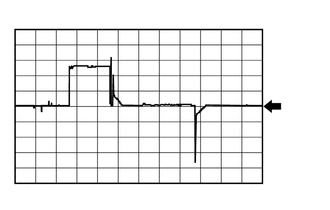
Using an oscilloscope, check waveform 2.
- NOTICE:
-
The oscilloscope waveform shown in the illustration is an example for reference only. Noise, chattering, etc. are not shown.
| Item | Condition |
|---|---|
| Tester Connection | A105-4 (UL1) - A105-2 (GND1) |
| Tool setting | 5 V/DIV., 200 ms./DIV. |
| Vehicle condition | Center door fully closed → center door open operation |
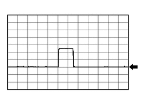
Using an oscilloscope, check waveform 3.
- NOTICE:
-
The oscilloscope waveform shown in the illustration is an example for reference only. Noise, chattering, etc. are not shown.
| Item | Condition |
|---|---|
| Tester Connection | A105-14 (UL2) - A105-2 (GND1) |
| Tool setting | 5 V/DIV., 200 ms./DIV. |
| Vehicle condition | Center door fully closed → center door open operation |
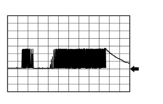
Using an oscilloscope, check waveform 4.
- NOTICE:
-
The oscilloscope waveform shown in the illustration is an example for reference only. Noise, chattering, etc. are not shown.
| Item | Condition |
|---|---|
| Tester Connection | A105-9 (UL+) - A105-2 (GND1) |
| Tool setting | 5 V/DIV., 1 s./DIV. |
| Vehicle condition | Center door close operation → closer operation → center door fully closed |
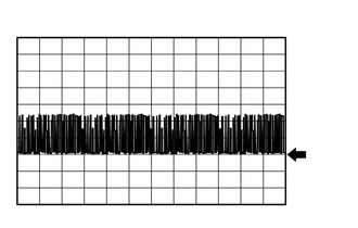
Using an oscilloscope, check waveform 5.
- NOTICE:
-
The oscilloscope waveform shown in the illustration is an example for reference only. Noise, chattering, etc. are not shown.
| Item | Condition |
|---|---|
| Tester Connection | A105-11 (UL) - A105-10 (E) |
| Tool setting | 5 V/DIV., 1 ms./DIV. |
| Vehicle condition | Magnetic clutch is engaged |
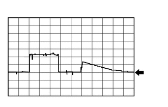
Using an oscilloscope, check waveform 6.
- NOTICE:
-
The oscilloscope waveform shown in the illustration is an example for reference only. Noise, chattering, etc. are not shown.
| Item | Condition |
|---|---|
| Tester Connection | A105-12 (DC+) - A105-2 (GND1) |
| Tool setting | 5 V/DIV., 500 ms./DIV. |
| Vehicle condition | Center door close operation → closer operation → center door fully closed |
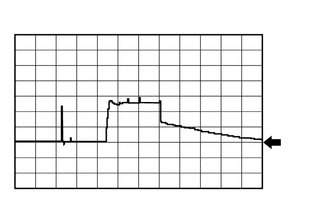
Using an oscilloscope, check waveform 7.
- NOTICE:
-
The oscilloscope waveform shown in the illustration is an example for reference only. Noise, chattering, etc. are not shown.
| Item | Condition |
|---|---|
| Tester Connection | A105-13 (DC-) - A105-2 (GND1) |
| Tool setting | 5 V/DIV., 500 ms./DIV. |
| Vehicle condition | Center door close operation → closer operation → center door fully closed |
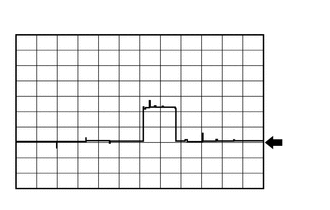
Using an oscilloscope, check waveform 8.
- NOTICE:
-
The oscilloscope waveform shown in the illustration is an example for reference only. Noise, chattering, etc. are not shown.
| Item | Condition |
|---|---|
| Tester Connection | ·
A106-2 (DC+) - A106-6 (SGND) ·
A106-5 (DC-) - A106-6 (SGND) |
| Tool setting | 5 V/DIV., 500 ms./DIV. |
| Vehicle condition | Center door close operation → closer operation → center door fully closed |
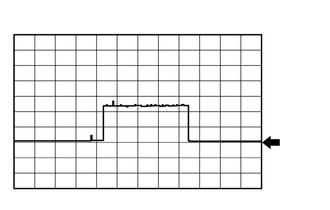
Using an oscilloscope, check waveform 9.
- NOTICE:
-
The oscilloscope waveform shown in the illustration is an example for reference only. Noise, chattering, etc. are not shown.
| Item | Condition |
|---|---|
| Tester Connection | ·
A106-11 (LMT) - A106-6 (SGND) ·
A107-16 (P/W) - A107-4 (SGND) |
| Tool setting | 5 V/DIV., 500 ms./DIV. |
| Vehicle condition | Center door close operation → closer operation → center door fully closed |
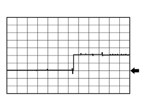
Using an oscilloscope, check waveform 10.
- NOTICE:
-
The oscilloscope waveform shown in the illustration is an example for reference only. Noise, chattering, etc. are not shown.
| Item | Condition |
|---|---|
| Tester Connection | ·
A106-17 (FUL) - A106-6 (SGND) ·
A106-20 (HAF) - A106-6 (SGND) ·
A107-24 (HAF) - A107-4 (SGND) |
| Tool setting | 5 V/DIV., 500 ms./DIV. |
| Vehicle condition | Center door close operation → closer operation → center door fully closed |
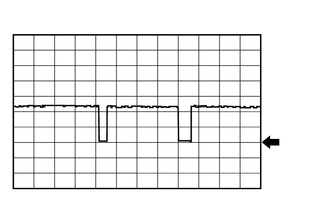
Using an oscilloscope, check waveform 11.
- NOTICE:
-
The oscilloscope waveform shown in the illustration is an example for reference only. Noise, chattering, etc. are not shown.
| Item | Condition |
|---|---|
| Tester Connection | ·
A106-19 (POL) - A106-6 (SGND) ·
A107-20 (L+) - A107-4 (SGND) |
| Tool setting | 5 V/DIV., 500 ms./DIV. |
| Vehicle condition | Center door close operation → closer operation → center door fully closed |
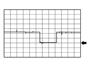
Using an oscilloscope, check waveform 12.
- NOTICE:
-
The oscilloscope waveform shown in the illustration is an example for reference only. Noise, chattering, etc. are not shown.
| Item | Condition |
|---|---|
| Tester Connection | A106-23 (LSWD) - A106-6 (SGND) |
| Tool setting | 5 V/DIV., 500 ms./DIV. |
| Vehicle condition | Center door close operation → closer operation → center door fully closed |
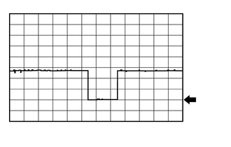
Using an oscilloscope, check waveform 13.
- NOTICE:
-
The oscilloscope waveform shown in the illustration is an example for reference only. Noise, chattering, etc. are not shown.
| Item | Condition |
|---|---|
| Tester Connection | A107-17 (SIG) - A107-4 (SGND) |
| Tool setting | 5 V/DIV., 200 ms./DIV. |
| Vehicle condition | Center door fully closed → center door open operation |
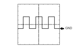
Using an oscilloscope, check waveform 14.
- NOTICE:
-
The oscilloscope waveform shown in the illustration is an example for reference only. Noise, chattering, etc. are not shown.
| Item | Condition |
|---|---|
| Tester Connection | A107-25 (SPD) - A107-4 (SGND) |
| Tool setting | 5 V/DIV., 20 ms./DIV. |
| Vehicle condition | Vehicle being driven at approximately 5 km/h (3 mph) |
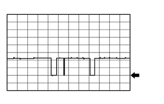
Using an oscilloscope, check waveform 15.
- NOTICE:
-
The oscilloscope waveform shown in the illustration is an example for reference only. Noise, chattering, etc. are not shown.
| Item | Condition |
|---|---|
| Tester Connection | A107-26 (SW) - A107-4 (SGND) |
| Tool setting | 5 V/DIV., 500 ms./DIV. |
| Vehicle condition | Center door close operation → closer operation → center door fully closed |