RM2850E
_51
Engine / Hybrid System
_082614
N04C-WA EMISSION CONTROL
_0400651
UREA SELECTIVE CATALYTIC REDUCTION SYSTEM
U
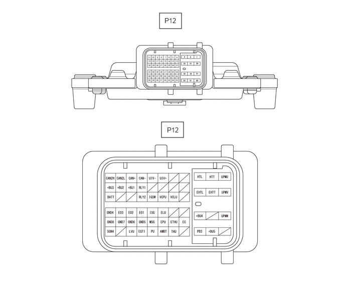
N04C-WA EMISSION CONTROL UREA SELECTIVE CATALYTIC REDUCTION SYSTEM TERMINALS OF ECM
TERMINALS OF DCU (EMISSION CONTROL ECU ASSEMBLY)
3.313,0.271 3.771,0.594
0.458,0.323
3.354,2.531 3.813,2.854
0.458,0.323
3.417,0.344 3.74,0.542
0.323,0.198
10
false
P12
3.469,2.615 3.792,2.813
0.323,0.198
10
false
P12
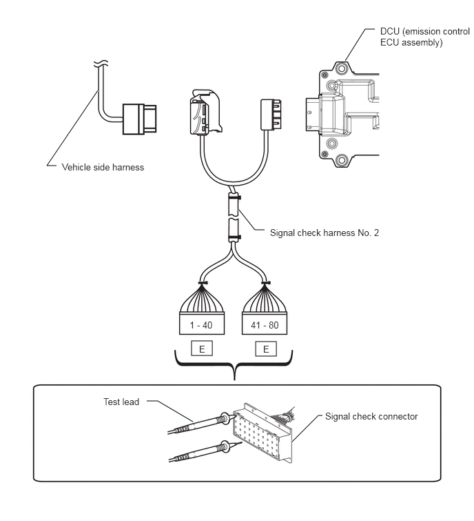
SST (SIGNAL CHECK HARNESS NO. 2) CONNECT
Since the DCU (emission control ECU assembly) uses waterproof connectors, the connectors cannot be inspected directly.
To prevent damage of the DCU (emission control ECU assembly) connector, connect the signal check harness No. 2 and perform measuring by bringing the test probe into contact with the signal check harness No. 2 side.
- SST
- 09843-E7020
2.896,5.146 3.208,5.365
0.313,0.219
3.865,5.156 4.177,5.375
0.313,0.219
1.479,1.365 0.708,2.5
0.708,2.5 0.854,2.5
true
5.219,0.917 5.521,0.438
5.521,0.438 5.667,0.438
true
2.917,6.365 2.385,6.052
2.385,6.052 2.219,6.052
true
4.406,6.677 4.813,6.271
4.813,6.271 4.875,6.271
true
3.604,3.156 3.854,3.469
3.854,3.469 4,3.469
true
5.75,0.385 7.135,0.76
1.385,0.375
10
false
DCU (emission control ECU assembly)
4.083,3.427 6.063,3.677
1.979,0.25
10
false
Signal check harness No. 2
0.938,2.438 2.521,2.615
1.583,0.177
10
false
Vehicle side harness
3.01,5.188 3.365,5.417
0.354,0.229
10
false
E
2.865,4.823 3.292,5.073
0.427,0.25
10
false
1 - 40
3.792,4.823 4.302,5.063
0.51,0.24
10
false
41 - 80
4.917,6.198 6.646,6.521
1.729,0.323
10
false
Signal check connector
1.563,5.979 3.229,6.188
1.667,0.208
10
false
Test lead
3.979,5.188 4.333,5.417
0.354,0.229
10
false
E
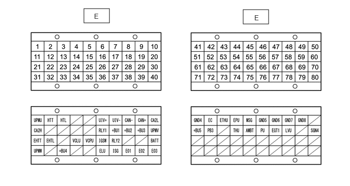
Signal Check Connector
1.719,0.177 2.24,0.469
0.521,0.292
4.979,0.198 5.5,0.49
0.521,0.292
1.927,0.25 2.083,0.448
0.156,0.198
10
false
E
5.208,0.281 5.365,0.479
0.156,0.198
10
false
E
| Terminal No. (Symbol) | Terminal Description |
|---|---|
| E-1 (UPMU) | Pump motor operation signal (U-phase) |
| E-2 (HTT) | Tank heater operation signal (+) |
| E-3 (HTL) | Urea solution pipe heater operation signal (+) |
| E-6 (UIV+) | Urea injector assembly operation signal (+) |
| E-7 (UIV-) | Urea injector assembly operation signal (-) |
| E-8 (CAN-) | CAN communication line |
| E-9 (CAN+) | CAN communication line |
| E-10 (CA2L) | CAN communication line |
| E-11 (CA2H) | CAN communication line |
| E-16 (RLY1) | ABS MTR/DCU relay operation signal |
| E-17 (+BU1) | Power source of DCU (emission control ECU assembly) |
| E-18 (+BU2) | Power source of DCU (emission control ECU assembly) |
| E-19 (+BU3) | Power source of DCU (emission control ECU assembly) |
| E-20 (UPMV) | Pump motor operation signal (V-phase) |
| E-21 (EHTT) | Tank heater operation signal (-) |
| E-22 (EHTL) | Urea solution pipe heater operation signal (-) |
| E-24 (VCLU) | Power source of level sensor (urea pump) |
| E-25 (VCPU) | Power source of pressure sensor (urea pump) |
| E-26 (IGSW) | Ignition switch |
| E-27 (RLY2) | UREA HTR relay operation signal |
| E-30 (BATT) | Battery (for measuring the battery voltage and for the DCU (emission control ECU assembly) memory) |
| E-31 (UPMW) | Pump motor operation signal (W-phase) |
| E-33 (+BU4) | Power source of heater |
| E-36 (ELU) | Ground circuit of level sensor (urea pump) |
| E-37 (ISG) | Shielded ground circuit of pressure sensor (urea pump) |
| E-38 (E01) | Ground circuit of DCU (emission control ECU assembly) |
| E-39 (E02) | Ground circuit of DCU (emission control ECU assembly) |
| E-40 (E03) | Ground circuit of DCU (emission control ECU assembly) |
| E-41 (GND4) | Ground circuit of DCU (emission control ECU assembly) |
| E-42 (EC) | Ground circuit of DCU (emission control ECU assembly) |
| E-43 (ETHU) | Ground circuit of temperature sensor (urea pump) |
| E-44 (EPU) | Ground circuit of pressure sensor (urea pump) |
| E-45 (MSG) | Shielded ground circuit of urea pump |
| E-46 (GND5) | Ground circuit of DCU (emission control ECU assembly) |
| E-47 (GND6) | Ground circuit of DCU (emission control ECU assembly) |
| E-48 (GND7) | Ground circuit of DCU (emission control ECU assembly) |
| E-49 (GND8) | Ground circuit of DCU (emission control ECU assembly) |
| E-51 (+BU5) | Power source of heater |
| E-52 (PB3) | Power source of heater |
| E-54 (THU) | Temperature sensor (urea pump) |
| E-55 (AMBT) | Ambient temperature sensor (cooler thermistor) |
| E-56 (PU) | Pressure sensor (urea pump) |
| E-57 (EGT1) | No. 5 exhaust gas temperature sensor |
| E-58 (LVU) | Level sensor (urea pump) |
| E-60 (SGN4) | Ground circuit of ambient temperature sensor (cooler thermistor) and No. 5 exhaust gas temperature sensor |