N04C-VL ENGINE MECHANICAL ENGINE UNIT REPLACEMENT
CAUTION / NOTICE / HINT
- HINT:
-
There are 2 methods to replace the timing chain or belt cover oil seal.
PROCEDURE

 11301C
1.REPLACE TIMING CHAIN OR BELT COVER OIL SEAL
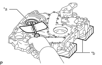
| *a | Protective Tape |
| *b | Wooden Block |
If the timing gear cover is removed from the cylinder block:
Using a screwdriver with its tip wrapped in protective tape, pry out the oil seal.
- HINT:
-
Use wooden blocks and a piece of cloth to prevent damage to the timing gear cover.
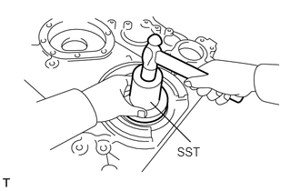
Using SST and a hammer, tap in a new oil seal to the timing gear cover so that oil seal is flush with the timing gear edge.
- SST
- 09223-78010
- NOTICE:
- ·
Be careful not to tap the oil seal at an angle.
·Keep the gap between the gear case edge and the oil seal free of foreign matter.
Apply MP grease to the oil seal lip.
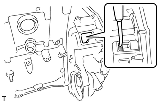
If the timing gear cover is installed onto the cylinder block:
Using a 46 mm socket wrench, remove the nut, spacer and crankshaft pulley.
- HINT:
-
Insert a screwdriver through the inspection hole of the flywheel housing into the ring gear of the flywheel to keep it from turning together with the crankshaft.
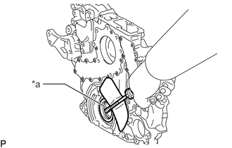
| *a | Protective Tape |
Using a screwdriver with its tip wrapped in protective tape, pry out the oil seal.
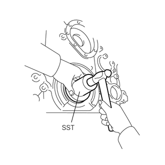
Using SST and a hammer, tap in a new oil seal into the timing gear cover so that oil seal is flush with the timing gear edge.
- SST
- 09223-78010
- NOTICE:
- ·
Be careful not to tap the oil seal at an angle.
·Keep the gap between the gear case edge and the oil seal free of foreign matter.
Apply MP grease to the oil seal lip.
Install the pulley and spacer onto the crankshaft.
- HINT:
-
Align the pulley set key with the key groove of the pulley.
Using a 46 mm socket wrench, tighten the nut.
- Torque:
100 N*m (1020 kgf*cm, 74 ft.*lbf)
- HINT:
-
Insert a screwdriver through the inspection hole of the flywheel housing into the ring gear of the flywheel to keep it from turning together with the crankshaft.
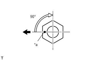
Mark the front side of the nut with paint as shown in the illustration.
| *a | Paint Mark |

|
Right Side of Engine |
Retighten the nut by 90°.
11381A
2.REPLACE REAR ENGINE OIL SEAL
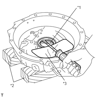
Using a screwdriver with its tip wrapped in protective tape, pry out the oil seal.
| *1 | Protective Tape |
| *2 | Wooden Blocks |
| *3 | Piece of Cloth |
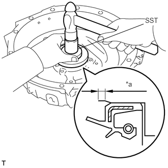
Using SST and a hammer, tap in a new oil seal until it is 4 mm (0.157 in.) below the upper edge of the flywheel housing.
- SST
- 09223-78010
| *a | 4 mm (0.157 in.) |
- NOTICE:
- ·
Be careful not to tap the oil seal at an angle.
·Keep the gap between the rear oil seal retainer edge and the oil seal free of foreign matter.
Apply MP grease to the oil seal lip.
3.REPLACE STRAIGHT PIN
- NOTICE:
-
It is not necessary to remove the straight pins unless they are being replaced.
Remove the 7 straight pins.
Using a plastic-faced hammer, install 7 new straight pins.
- Standard Protrusion Height:
Item Specified Condition A 6.0 mm (0.236 in.) B 13.0 mm (0.512 in.) C 16.0 mm (0.630 in.) D 6.0 mm (0.236 in.)
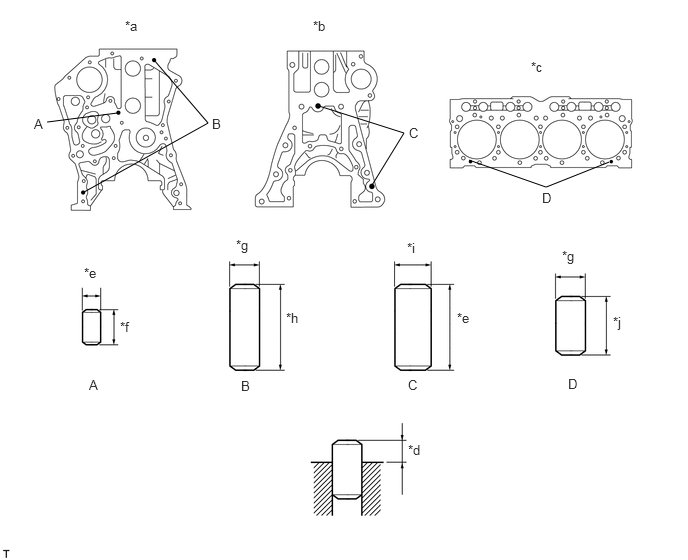
| *a | Front Side | *b | Rear Side |
| *c | Cylinder Head Side | *d | Protrusion Height |
| *e | 5.0 mm (0.197 in.) | *f | 10.0 mm (0.394 in.) |
| *g | 8.0 mm (0.315 in.) | *h | 24.0 mm (0.945 in.) |
| *i | 12.0 mm (0.472 in.) | *j | 16.0 mm (0.630 in.) |