N04C-WA ENGINE MECHANICAL CYLINDER HEAD REPLACEMENT
PROCEDURE

 11131
1.REPLACE INTAKE VALVE SEAT
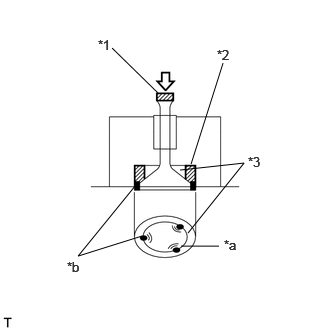
| *1 | Brass Block |
| *2 | Intake Valve Seat |
| *3 | Intake Valve |
| *a | Grind these Points with a Grinder |
| *b | Weld Application Point |
As shown in the illustration, grind the 3 points on the circumference of an unneeded intake valve and weld it to the intake valve seat.
- NOTICE:
-
To protect the lower surface of the cylinder head sub-assembly from welding spatters, be sure to apply grease to the cylinder head sub-assembly before welding.
Place a brass block on the top of the valve stem and strike it with a hammer to remove the intake valve seat.
- CAUTION:
-
When striking, metal shards may fly off on impact. Wear safety glasses to protect your eyes.
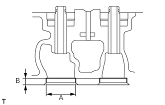
Using a caliper gauge and vernier caliper, measure the dimensions of the valve seat installation holes.
- Standard Intake Valve Seat Dimensions:
Item Specification Condition If the result is not specified, replace the cylinder head sub-assembly.
A 36.000 to 36.016 mm (1.4173 to 1.4179 in.) B 8.4 to 8.6 mm (0.331 to 0.339 in.)
Heat the cylinder head sub-assembly up to 80 to 100°C (176 to 212°F).
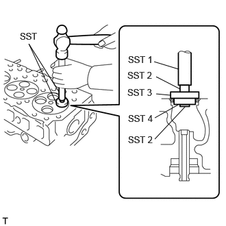
Using SST and a hammer, lightly tap new intake valve seats into the cylinder head sub-assembly.
- SST
- 09950-60011 (09951-00300, 09951-00360, 09952-06010)
09950-70010 (09951-07100)
| SST 1 | 09951-07100 |
| SST 2 | 09952-06010 |
| SST 3 | 09951-00360 |
| SST 4 | 09951-00300 |
Using SST and a hammer, completely tap in the intake valve seats.
- SST
- 09950-60011 (09951-00300, 09951-00360, 09952-06010)
09950-70010 (09951-07100)
11135
2.REPLACE EXHAUST VALVE SEAT
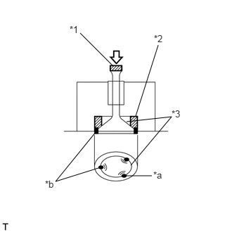
| *1 | Brass Block |
| *2 | Exhaust Valve Seat |
| *3 | Exhaust Valve |
| *a | Grind these Points with a Grinder |
| *b | Weld Application Point |
As shown in the illustration, grind the 3 points on the circumference of an unneeded exhaust valve and weld it to the exhaust valve seat.
- NOTICE:
-
To protect the lower surface of the cylinder head sub-assembly from welding spatters, be sure to apply grease to the cylinder head sub-assembly before welding.
Place a brass block on the top of the valve stem and strike it with a hammer to remove the valve seat.
- CAUTION:
-
When striking, metal shards may fly off on impact. Wear safety glasses to protect your eyes.
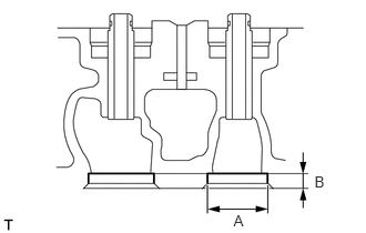
Using a caliper gauge and vernier caliper, measure the dimensions of the valve seat installation holes.
- Standard Exhaust Valve Seat Dimensions:
Item Specified Condition If the result is not specified, replace the cylinder head sub-assembly.
A 32.000 to 32.016 mm (1.2598 to 1.2602 in.) B 7.6 to 7.8 mm (0.299 to 0.307 in.)
Heat the cylinder head sub-assembly up to 80 to 100°C (176 to 212°F).
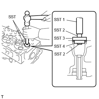
Using SST and a hammer, lightly tap new exhaust valve seats into the cylinder head sub-assembly.
- SST
- 09950-60011 (09951-00250, 09951-00320, 09952-06010)
09950-70010 (09951-07100)
| SST 1 | 09951-07100 |
| SST 2 | 09952-06010 |
| SST 3 | 09951-00360 |
| SST 4 | 09951-00300 |
Using SST and a hammer, completely tap in the exhaust valve seats.
- SST
- 09950-60011 (09951-00250, 09951-00320, 09952-06010)
09950-70010 (09951-07100)
11122
3.REPLACE INTAKE VALVE GUIDE BUSH
Heat the cylinder head sub-assembly up to 80 to 100°C (176 to 212°F).
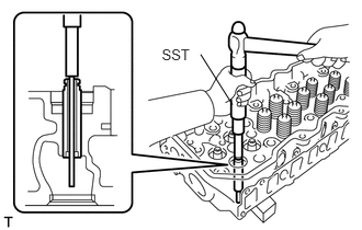
Using SST and a hammer, tap out the intake valve guide bush.
- SST
- 09201-10000 (09201-01070)
09950-70010 (09951-07100)
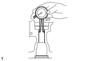
Using a caliper gauge, measure the inside diameter of the intake valve guide bush.
- Standard bush inside diameter:
13.000 to 13.018 mm (0.512 to 0.513 in.)
- HINT:
-
If the bush bore diameter of the cylinder head sub-assembly is more than 13.02 mm (0.515 in.), replace the cylinder head sub-assembly.
Heat the cylinder head sub-assembly up to 80 to 100°C (176 to 212°F).
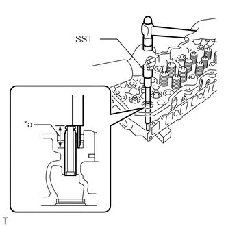
| *a | Protrusion height |
Using SST, tap in a new intake valve guide bush.
- SST
- 09201-10000 (09201-01070)
09950-70010 (09951-07100)
- Standard protrusion height:
26.4 to 26.8 mm (1.04 to 1.06 in.)
- NOTICE:
-
Do not tap in the intake valve guide bush excessively.
Using a reamer, ream the inside of the intake valve guide bush to the specified oil clearance between the intake valve guide bush and intake valve stem.
- Standard oil clearance:
0.028 to 0.058 mm (0.00110 to 0.00228 in.)
- Maximum oil clearance:
0.12 mm (0.00472 in.)
11126
4.REPLACE EXHAUST VALVE GUIDE BUSH
Heat the cylinder head sub-assembly up to 80 to 100°C (176 to 212°F).
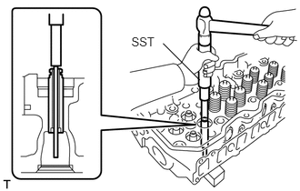
Using SST and a hammer, tap out the exhaust valve guide bush.
- SST
- 09201-10000 (09201-01070)
09950-70010 (09951-07100)
Using a caliper gauge, measure the inside diameter of the exhaust valve guide bush.
- Standard bush inside diameter:
13.000 to 13.018 mm (0.512 to 0.513 in.)
- HINT:
-
If the bush bore diameter of the cylinder head sub-assembly is more than 13.02 mm (0.5125 in.), replace the cylinder head sub-assembly.
Heat the cylinder head sub-assembly up to 80 to 100°C (176 to 212°F).
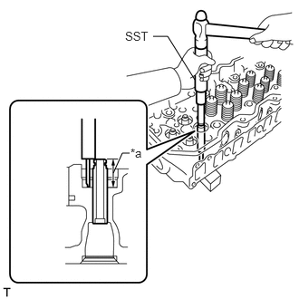
| *a | Protrusion height |
Using SST, tap in a new exhaust valve guide bush.
- SST
- 09201-10000 (09201-01070)
09950-70010 (09951-07100)
- Standard protrusion height:
26.4 to 26.8 mm (1.04 to 1.06 in.)
- NOTICE:
-
Do not tap in the exhaust valve guide bush excessively.
Using a reamer, ream the inside of the exhaust valve guide bush to the specified oil clearance between the exhaust valve guide bush and exhaust valve stem.
- Standard oil clearance:
0.053 to 0.083 mm (0.00209 to 0.00327 in.)
- Maximum oil clearance:
0.15 mm (0.00591 in.)
11176
5.REPLACE INJECTION NOZZLE SEAT
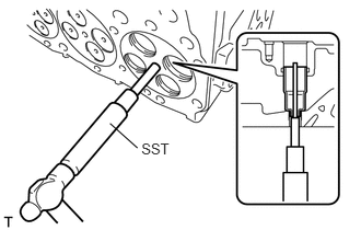
Using SST, remove the injection nozzle seat.
- SST
- 09201-10000 (09201-01050)
09950-70010 (09951-07100)
Remove the O-ring from the cylinder head sub-assembly.
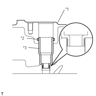
| *1 | Cylinder Head Sub-assembly |
| *2 | O-Ring |
| *3 | Injection Nozzle Seat |
Apply a light coat of engine oil to new O-rings, and install them into the cylinder head sub-assembly.
- NOTICE:
-
Be sure to install new O-rings. Reusing O-rings may cause water or gas leakage and lead to overheating or a cracked cylinder head sub-assembly.
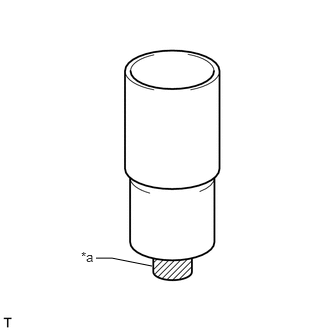
| *a | Seal Packing |
Apply seal packing to new injection nozzle seats.
- Seal packing:
Toyota Genuine Seal Packing Black, Three Bond 1207B or equivalent
- NOTICE:
- ·
Remove any oil from the installation surfaces of the cylinder head sub-assembly and injection nozzle seats.
·Be sure to install new injection nozzle seats. Reusing injection nozzle seats may cause water or gas leakage and lead to overheating or a cracked cylinder head sub-assembly.
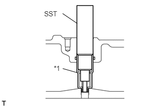
| *1 | Injection Nozzle Seat |
Using SST, install the injection nozzle seat onto the cylinder head sub-assembly.
- SST
- 09260-69015 (09268-06020)
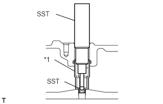
| *1 | Injection Nozzle Seat |
Using SST, stake the injection nozzle seat.
- SST
- 09260-69015 (09268-06010)
- NOTICE:
-
Put a container under the cylinder head sub-assembly to prevent the steel ball from being lost.