RM2850E
_58
Vehicle Interior
_073207
AIR CONDITIONING
_0403623
PRESSURE SWITCH(except 1BZ-FPE)
G
AIR CONDITIONING PRESSURE SWITCH(except 1BZ-FPE) ON-VEHICLE INSPECTION
PROCEDURE

 88645H
1.INSPECT NO. 1 PRESSURE SWITCH
a.
0.104,0.083 0.417,0.281
0.313,0.198
10
false
*a
0.167,2.083 0.479,2.281
0.313,0.198
10
false
*b
0.188,2.49 0.5,2.688
0.313,0.198
10
false
*c
0.667,2.385 0.979,2.583
0.313,0.198
10
false
*e
1.938,2 2.25,2.198
0.313,0.198
10
false
*d
1.042,1.875 1.25,2.083
0.208,0.208
10
false
A
2.542,1.875 2.75,2.083
0.208,0.208
10
false
B
0.708,2.667 0.917,2.875
0.208,0.208
10
false
C
1.25,2.667 1.458,2.875
0.208,0.208
10
false
D
2.875,2.667 3.083,2.875
0.208,0.208
10
false
E
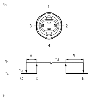
| *a | Component without harness connected
(No. 1 Pressure Switch) |
| *b | Continuity |
| *c | No Continuity |
| *d | ON (Below 1 Ω) |
| *e | OFF (10 kΩ or higher) |
High pressure side check
i.
Install the air conditioning tool set.
ii.
Check the continuity between connector terminals 1 and 4.
- Standard:
Due to the coolant pressure, the values are as shown in the illustration.
- Specified Condition:
A 20 kPa (0.2 kgf/cm2, 3 psi) B 390 to 790 kPa (4.0 to 8.1 kgf/cm2, 57 to 115 psi) C 176 to 216 kPa (1.8 to 2.2 kgf/cm2, 26 to 31 psi) D 196 to 250 kPa (2.0 to 2.5 kgf/cm2, 28 to 36 psi) E 2940 to 3190 kPa (30.0 to 32.5 kgf/cm2, 426 to 463 psi)
b.
0.083,0.094 0.396,0.25
0.313,0.156
10
false
*a
0.75,2.177 1.063,2.333
0.313,0.156
10
false
*b
0.75,2.51 1.063,2.667
0.313,0.156
10
false
*c
1.24,2.438 1.552,2.594
0.313,0.156
10
false
*e
2.354,2.052 2.667,2.208
0.313,0.156
10
false
*d
1.552,2.656 1.865,2.813
0.313,0.156
10
false
A
2.177,2.656 2.49,2.813
0.313,0.156
10
false
B
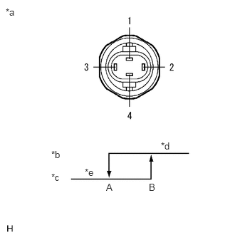
| *a | Component without harness connected
(No. 1 Pressure Switch) |
| *b | Continuity |
| *c | No Continuity |
| *d | ON (Below 1 Ω) |
| *e | OFF (10 kΩ or higher) |
Middle pressure side check
i.
Check the continuity between connector terminals 2 and 3.
- Standard:
Due to the coolant pressure, the values are as shown in the illustration.
- Specified Condition:
A 1110 to 1350 kPa (11.3 to 13.8 kgf/cm2, 161 to 196 psi) B 1440 to 1600 kPa (14.7 to 16.3 kgf/cm2, 209 to 232 psi)