N04C-VJ FUEL FUEL TANK INSTALLATION
PROCEDURE

 1.INSTALL FUEL TANK CUSHION
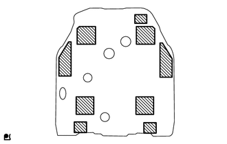
Install 9 new fuel tank cushions.
77011
2.INSTALL LOWER FUEL TANK FILLER PIPE SUB-ASSEMBLY
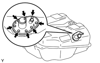
Install a new gasket and lower fuel tank filler pipe sub-assembly with the 8 screws.
- Torque:
- 3.0 N*m (31 kgf*cm, 27 in.*lbf)
77201A
3.INSTALL FUEL TANK INLET PIPE FUEL HOSE
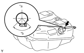
| *a | Upper |
| *b | 110° |
Install the fuel tank inlet pipe fuel hose to the lower fuel tank filler pipe and tighten the clamp.
77213B
4.INSTALL FUEL TANK TO FILLER PIPE HOSE
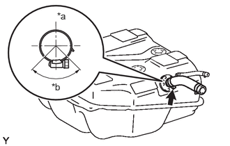
| *a | Upper |
| *b | 110° |
Install the fuel tank to filler pipe hose to the lower fuel tank filler pipe and tighten the clamp.
77420
5.INSTALL NO. 2 FUEL CUT OFF VALVE ASSEMBLY
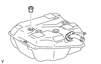
Install the No. 2 fuel cut off valve assembly to the fuel tank.
77380
6.INSTALL FUEL CUT OFF VALVE ASSEMBLY
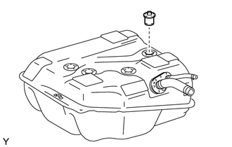
Install the fuel cut off valve assembly to the fuel tank.
77026A
7.INSTALL NO. 1 FUEL EVAPORATION TUBE SUB-ASSEMBLY
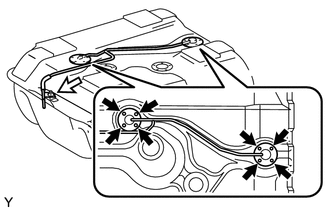

|
Screw |

|
Nut |
Install 2 new gaskets and the No. 1 fuel evaporation tube with the 8 screws and nut.
- Torque:
- Nut : 3.0 N*m (31 kgf*cm, 27 in.*lbf)
- Screw : 1.5 N*m (15 kgf*cm, 13 in.*lbf)
77017B
8.INSTALL FUEL TANK VENT TUBE SUB-ASSEMBLY
Install the grommet to the fuel tank.
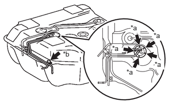
| *a | Screw |
| *b | Bolt |
Install a new gasket and the fuel tank vent tube with the 6 screws.
- Torque:
- 3.0 N*m (31 kgf*cm, 27 in.*lbf)
Install the bolt.
83320
9.INSTALL FUEL SENDER GAGE ASSEMBLY
77100
10.INSTALL FUEL TANK ASSEMBLY
Set the fuel tank on an engine lifter.
Raise the engine lifter.
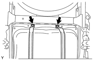
Connect the 2 fuel tank bands with the 2 bolts.
- Torque:
- 45 N*m (459 kgf*cm, 33 ft.*lbf)
77201A
11.CONNECT FUEL TANK INLET PIPE FUEL HOSE
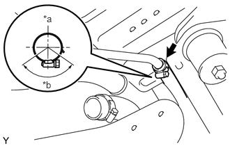
| *a | Upper |
| *b | 110° |
Connect the fuel tank inlet pipe fuel hose and tighten the clamp.
77213B
12.CONNECT FUEL TANK TO FILLER PIPE HOSE
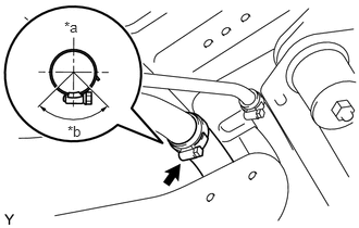
| *a | Upper |
| *b | 90° |
Connect the fuel tank to filler pipe hose and tighten the clamp.
77259D
13.CONNECT NO. 1 FUEL HOSE
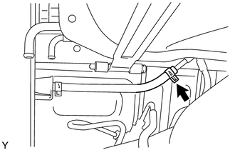
Connect the No. 1 fuel hose with the clamp.
77259E
14.CONNECT FUEL HOSE
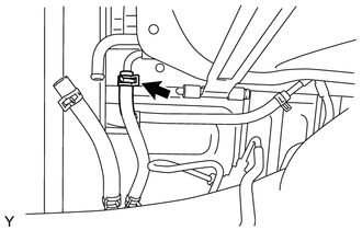
Connect the fuel hose with the clamp.
77254D
15.CONNECT a FUEL HOSE
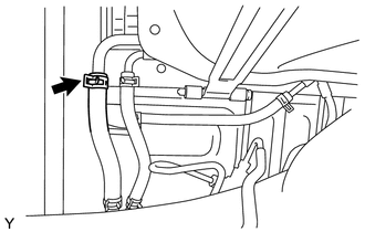
Connect the fuel hose with the clamp.
58750
16.INSTALL FUEL TANK INSPECTION HOLE COVER ASSEMBLY
Connect the fuel sender gauge assembly connector.
Install the fuel tank inspection hole cover assembly with the 2 screws.
17.BLEED AIR FROM FUEL SYSTEM
18.CONNECT CABLE TO NEGATIVE BATTERY TERMINAL
19.INSPECT FOR FUEL LEAK