RM2850E
_51
Engine / Hybrid System
_096895
N04C-VJ EXHAUST
_0461980
EXHAUST MANIFOLD
A
N04C-VJ EXHAUST EXHAUST MANIFOLD INSTALLATION
PROCEDURE

 17141
1.INSTALL EXHAUST MANIFOLD
a.
0.063,0.156 1.677,2.01
1.615,1.854
1.76,0.156 3.375,2.01
1.615,1.854
0.344,0.385 0.5,0.385
0.5,0.385 0.5,0.75
false
1.063,0.333 1.208,0.333
1.208,0.333 1.302,0.698
false
2.052,0.375 2.219,0.375
2.219,0.375 2.219,0.74
false
2.677,0.375 2.823,0.375
2.823,0.375 2.917,0.74
false
0.135,0.302 0.333,0.5
0.198,0.198
10
false
*1
0.865,0.26 1.073,0.458
0.208,0.198
10
false
*2
0.802,1.802 1.021,2.01
0.219,0.208
10
false
*a
2.594,1.792 2.813,2.01
0.219,0.219
10
false
*b
2.469,0.292 2.677,0.49
0.208,0.198
10
false
*2
1.854,0.292 2.063,0.49
0.208,0.198
10
false
*1
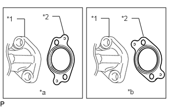
| *1 | Exhaust Manifold |
| *2 | Gasket |
| *a | INCORRECT |
| *b | CORRECT |
Install 4 new gaskets to the cylinder head sub-assembly as shown in the illustration.
b.
1.189,2.861 1.375,3.016
0.185,0.155
10
*a
2.193,2.861 2.378,3.016
0.185,0.155
10
*a
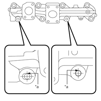
| *a | Contact |
Temporarily install the exhaust manifold.
- HINT:
-
The stud bolts should contact the exhaust manifold as shown in the illustration.
c.
0.052,0.052 3.365,2.24
3.313,2.188
0.052,2.302 3.365,4.49
3.313,2.188
0.083,0.104 0.302,0.302
0.219,0.198
10
false
*a
0.094,2.344 0.313,2.552
0.219,0.208
10
false
*b
0.354,0.292 0.583,0.49
0.229,0.198
10
false
12
1.083,0.292 1.469,0.5
0.385,0.208
10
false
3, 11
1.875,0.302 2.281,0.5
0.406,0.198
10
false
1, 10
2.792,0.302 2.938,0.51
0.146,0.208
10
false
9
0.531,1.833 0.698,2.052
0.167,0.219
10
false
5
2.927,1.833 3.083,2.031
0.156,0.198
10
false
8
1.271,1.833 1.604,2.01
0.333,0.177
10
false
2, 6
2.052,1.833 2.365,2.031
0.313,0.198
10
false
4, 7
1.333,4.167 1.5,4.365
0.167,0.198
10
false
3
2.125,4.167 2.302,4.385
0.177,0.219
10
false
1
2.917,4.156 3.063,4.354
0.146,0.198
10
false
5
0.542,4.167 0.698,4.354
0.156,0.188
10
false
7
0.396,2.635 0.542,2.833
0.146,0.198
10
false
8
1.188,2.635 1.333,2.833
0.146,0.198
10
false
4
1.99,2.635 2.156,2.833
0.167,0.198
10
false
2
2.792,2.635 2.938,2.844
0.146,0.208
10
false
6
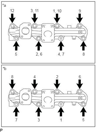
| *a | New Exhaust Manifold |
| *b | Used Exhaust Manifold |
Tighten the exhaust manifold in the order shown in the illustration using the 8 nuts, 4 exhaust pipe spacers and 4 spacers.
- Torque:
- 60 N*m (612 kgf*cm, 44 ft.*lbf)
- HINT:
-
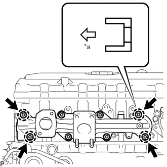 1.729,0.875 1.896,1.063 0.167,0.188 10 false *a
*a Exhaust Manifold Side
-
Make sure to install the 4 spacers shown in the illustration in the correct direction.
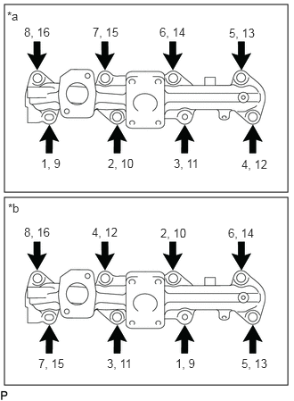
d.
0.052,0.052 3.365,2.24
3.313,2.188
0.052,2.302 3.365,4.49
3.313,2.188
0.083,0.104 0.313,0.281
0.229,0.177
10
false
*a
0.094,2.344 0.313,2.531
0.219,0.188
10
false
*b
1.083,0.292 1.458,0.469
0.375,0.177
10
false
7, 15
1.865,0.292 2.24,0.469
0.375,0.177
10
false
6, 14
0.281,0.292 0.656,0.469
0.375,0.177
10
false
8, 16
2.677,0.302 3.052,0.479
0.375,0.177
10
false
5, 13
2.823,1.833 3.198,2.01
0.375,0.177
10
false
4, 12
2.031,1.823 2.406,2
0.375,0.177
10
false
3, 11
1.26,1.823 1.635,2
0.375,0.177
10
false
2, 10
0.479,1.823 0.854,2
0.375,0.177
10
false
1, 9
0.281,2.625 0.656,2.802
0.375,0.177
10
false
8, 16
1.073,2.625 1.448,2.802
0.375,0.177
10
false
4, 12
1.875,2.635 2.25,2.813
0.375,0.177
10
false
2, 10
2.667,2.635 3.042,2.813
0.375,0.177
10
false
6, 14
0.448,4.156 0.833,4.354
0.385,0.198
10
false
7, 15
1.25,4.156 1.635,4.333
0.385,0.177
10
false
3, 11
2.052,4.156 2.375,4.333
0.323,0.177
10
false
1, 9
2.823,4.156 3.208,4.365
0.385,0.208
10
false
5, 13
| *a | New Exhaust Manifold |
| *b | Used Exhaust Manifold |
Retighten the exhaust manifold with the nuts and spacers in the order shown in the illustration.
- Torque:
- 60 N*m (612 kgf*cm, 44 ft.*lbf)
17107
2.INSTALL EXHAUST MANIFOLD HEAT INSULATOR SUB-ASSEMBLY
a.
Install the exhaust manifold heat insulator sub-assembly with the 3 bolts.
- Torque:
- 28.5 N*m (291 kgf*cm, 21 ft.*lbf)
17201
3.INSTALL TURBOCHARGER SUB-ASSEMBLY