N04C-VJ ENGINE CONTROL DIESEL THROTTLE BODY ON-VEHICLE INSPECTION
PROCEDURE

 26100
1.INSPECT VENTURI ASSEMBLY
Check the throttle control motor operation.
Remove the air hose from the venturi assembly.
Disconnect the throttle control motor connector.
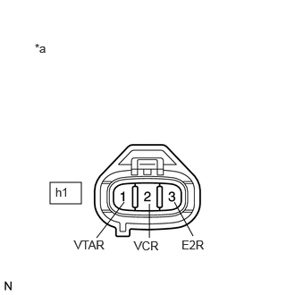
Measure the voltage according to the value(s) in the table below.
- Standard Voltage:
Tester Connection Switch Condition Specified Condition h1-2 (VCR) - Body ground Ignition switch ON 11 to 14 V
| *a | Front view of wire harness connector (to Throttle Control Motor) |
Connect the throttle control motor connector.
Turn the ignition switch to ON.
When the ignition switch is turned off, make sure that the valve of the venturi assembly operates.
- OK:
The throttle valve of the venturi assembly operates.
Install the air hose to the venturi assembly.
Check the throttle position sensor.
Connect the GTS to the DLC3.
Turn the ignition switch to ON and turn the GTS on.
Warm up the engine.
- HINT:
- ·
The water temperature is 60°C(140°F) or more.
·The fuel temperature is 20°C(68°F) or more.
Inspect the engine idling speed.
- Standard:
Condition Engine Idle Speed A/C switched off 550 to 650 rpm
- NOTICE:
-
The shift lever should be in the neutral position and A/C switch should be turned off.
Enter the following menus: Power train / Engine and ECT / Data List / Actual Throttle Position.
Check that the value of the throttle valve angle is within specification.
- Standard:
Engine Condition Throttle valve opening position expressed as percentage During idling 30 to 100 % 1500 rpm 0 to 10 %
If the results are not as specified, check the throttle body, wire harness and ECM.