TERMINALS OF ECU
System information · Vehicles built from Nov 2010
Versions by build date: Jul 2007 – Oct 2010 from Nov 2010
| CHECK COMBINATION METER ASSEMBLY |
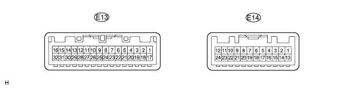

Measure the voltage and resistance of the wire harness side connectors.
Terminal No. (Symbol)
Wiring Color
Terminal Description
Condition
Specified Condition
E13-2 (IG+) - Body ground
R-L - Body ground
Ignition switch signal
Ignition switch off → ON
Below 1 V → 11 to 14 V
E13-1 (B) - Body ground
R - Body ground
Battery
Always
11 to 14 V
E13-9 (KSW) - Body ground
V-G - Body ground
Key unlock warning switch signal input
Key inserted → Key removed from ignition key cylinder
Below 1 V → 11 to 14 V
E13-29 (DOOR) - Body ground
W-L - Body ground
Driver door courtesy switch signal input
Driver door
closed → open
Below 1 V → 11 to 14 V
E13-21 (ES) - Body ground
W-B - Body ground
Ground
Always
Below 1 Ω
| CHECK MAIN BODY ECU (for LHD) |
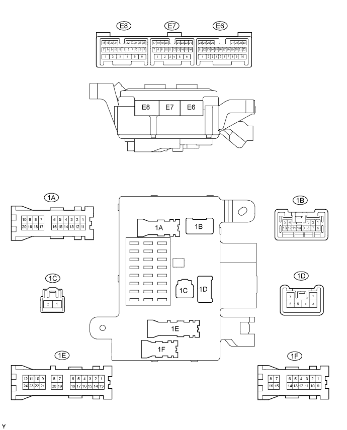
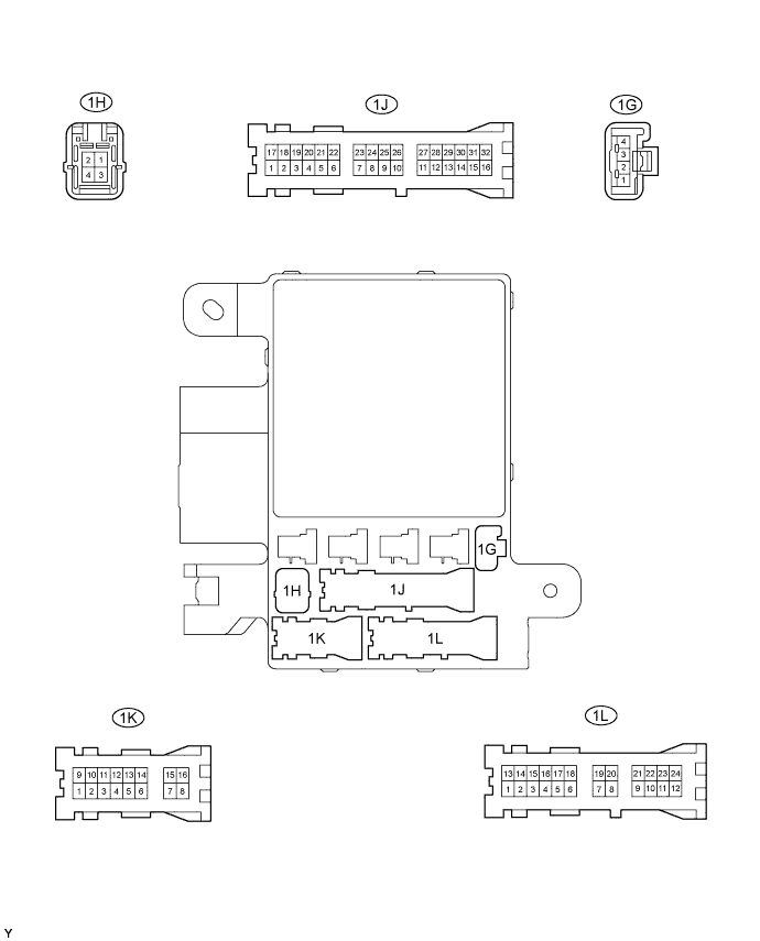
Measure the voltages of the wire harness side connectors.
Terminal No. (Symbol)
Wiring Color
Terminal Description
Condition
Specified Condition
E8-14 (KSW) - Body ground
G-Y - Body ground
Key unlock warning switch input
Key inserted →
Key removed from ignition key cylinder
Below 1 V → 9 to 14 V (or pulse generation)
1H-2 (GND1) - Body ground
W-B - Body ground
Ground
Always
Below 1 V
1B-4 (BECU) - Body ground
W-R - Body ground
Battery
Always
11 to 14 V
E7-23 (DCTY) - Body ground
R-B - Body ground
Driver door courtesy switch input
Driver door
closed → open
9 to 14 V (or pulse generation) → Below 1 V
E8-15 (KSWO) - Body ground
V-G - Body ground
Key unlock warning switch signal output
Key inserted → Key removed from ignition key cylinder
Below 1 V → 9 to 14 V (or pulse generation)
E8-11 (DCY2) - Body ground
W-L - Body ground
Driver door courtesy switch signal output
Driver door
closed → open
9 to 14 V (or pulse generation) → Below 1 V
| CHECK MAIN BODY ECU (for RHD) |
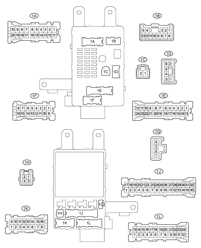
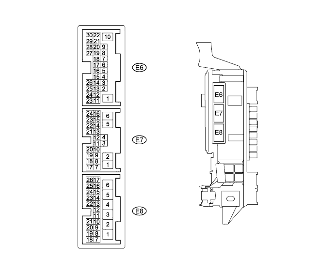
Measure the voltages of the wire harness side connectors.
Terminal No. (Symbol)
Wiring Color
Terminal Description
Condition
Specified Condition
E8-14 (KSW) - Body ground
G-Y - Body ground
Key unlock warning switch input
Key inserted →
Key removed from ignition key cylinder
Below 1 V → 9 to 14 V (or pulse generation)
1H-2 (GND1) - Body ground
W-B - Body ground
Ground
Always
Below 1 V
1L-4 (BECU) - Body ground
W-R - Body ground
Battery
Always
11 to 14 V
E7-23 (DCTY) - Body ground
R-B - Body ground
Driver door courtesy switch input
Driver door
closed → open
9 to 14 V (or pulse generation) → Below 1 V
E8-15 (KSWO) - Body ground
V-G - Body ground
Key unlock warning switch signal output
Key inserted → Key removed from ignition key cylinder
Below 1 V → 9 to 14 V (or pulse generation)
E8-11 (DCY2) - Body ground
W-L - Body ground
Driver door courtesy switch signal output
Driver door
closed → open
9 to 14 V (or pulse generation) → Below 1 V