INSPECTION
Inspection · Vehicles built from Jul 2007
| INSPECT INTEGRATION CONTROL AND PANEL ASSEMBLY |

Check the blower switch resistance.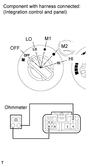

Measure the resistance according to the value(s) in the table below.
- Standard resistance:
Tester Connection
Switch Condition
Specified Condition
1 - 4 - 5 - 6 - 8
OFF
10 KΩ or higher
1 - 8
LO
Below 1 Ω
1 - 6 - 8
M1
Below 1 Ω
1 - 5 - 8
M2
Below 1 Ω
1 - 4 - 8
HI
Below 1 Ω
Check the illumination operation.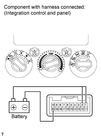
Connect the positive (+) lead from the battery to terminals 1 (IG+) and 2 (ILL+) and the negative (-) lead to terminal 20 (GND), then check that the illuminations light up.
- OK:
- Illuminations light up
Check the A/C indicator operation.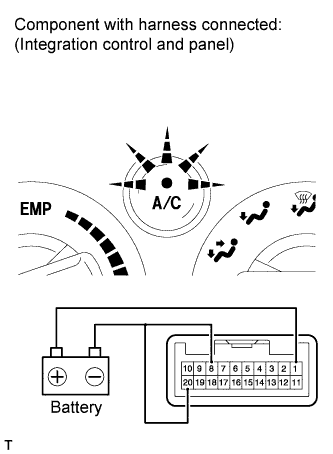
Connect the positive (+) lead from the battery to terminal 1 (IG+) and the negative (-) lead to terminals 8 (BLW) and 20 (GND).
Push the A/C button in and then check that the indicator lights up.
- OK:
Switch Condition
Specified Condition
Switch ON
Indicator illuminates
Switch OFF
Indicator turns OFF
Under the above condition, connect the positive (+) lead from the battery to terminal 2 (ILL+) and then check that the indicator dims.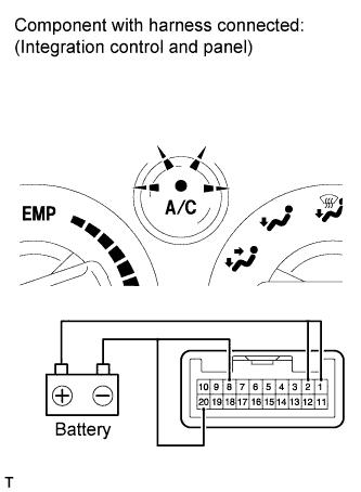
- OK:
Switch Condition
Specified Condition
Switch ON
Indicator dims
Switch OFF
Indicator turns OFF
Check the REC indicator operation.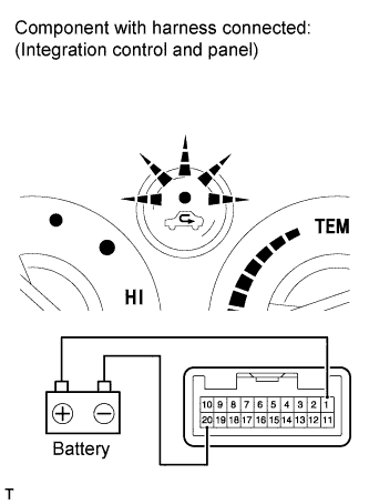
Connect the positive (+) lead from the battery to terminal 1 (IG+) and the negative (-) lead to terminal 20 (GND).
- NOTICE:
- Inspect the MODE switch in any position except DEF.
Push the REC button in and check that the indicator lights up.
- OK:
Switch Condition
Specified Condition
Switch ON
Indicator illuminates
Switch OFF
Indicator turns OFF
Under the above condition, connect the positive (+) lead from the battery to terminal 2 (ILL+) and then check that the indicator dims.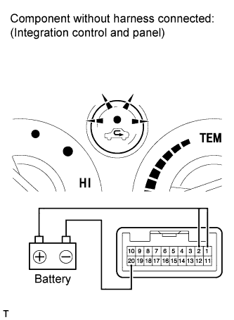
- NOTICE:
- Inspect the MODE switch in any position except DEF.
- OK:
Switch Condition
Specified Condition
Switch ON
Indicator dims
Switch OFF
Indicator turns OFF
Check MODE switch operation.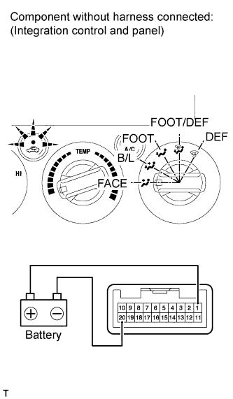
Connect the positive (+) lead from the battery to terminal 1 (IG+) and the negative (-) lead to terminal 20 (GND).
Check the REC indicator operation when the MODE switch is operated.
- OK:
Condition
Specified Condition (REC indicator)
MODE switch except DEF
REC switch ON ←→ OFF
Indicator turns ON ←→ OFF in accordance with REC switch operation
MODE switch DEF
REC switch ON ←→ OFF
Indicator turns OFF