Home › BODY ELECTRICAL › AUDIO / VISUAL › RADIO ANTENNA CORDINSTALLATION
Removal / installation · Vehicles built from Aug 2012
Versions by build date: Jul 2007 – Oct 2010 Nov 2010 – Jul 2012 from Aug 2012
CAUTION:
Some of these service operations affect the SRS airbag system. Read the precautionary notices concerning the SRS airbag system before servicing (Click here ).
1.
INSTALL ANTENNA CORD SUB-ASSEMBLY
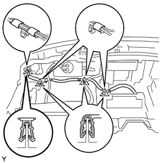
Install the antenna cord with 3 new pieces of tape. Engage the 4 clamps.
2.
INSTALL INSTRUMENT PANEL SUB-ASSEMBLY
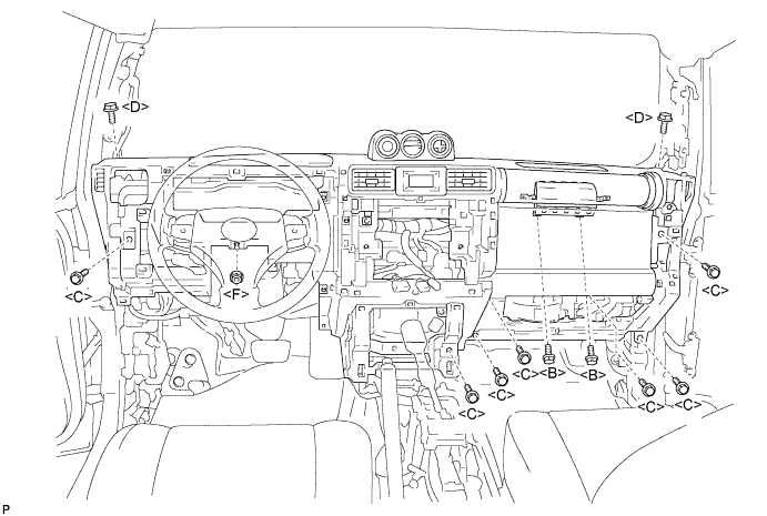
Install the lower instrument panel with the 2 <B> bolts, 2 <D> bolts, 7 <C> bolts and nut <F>.
Torque:
20 N*m{
204 kgf*cm
, 15 ft.*lbf
}
for bolt <B>
Engage the clamps and connect the connectors.
3.
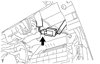
CONNECT PASSENGER AIRBAG CONNECTOR
Connect the passenger airbag connector.
4.
INSTALL INSTRUMENT PANEL FINISH PANEL END
Engage the 3 claws and install the instrument panel finish panel end.
5.
INSTALL FRONT NO. 2 SPEAKER ASSEMBLY
HINT:
Use the same procedure for both sides.
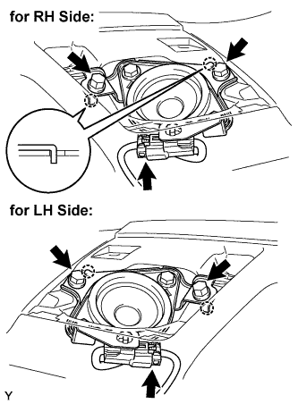
Connect the speaker connector.
Insert the 2 hooks into the instrument panel and install the front No. 2 speaker with the 2 bolts.
Torque:
2.5 N*m{
25 kgf*cm
, 22 in.*lbf
}
6.
INSTALL INSTRUMENT PANEL SPEAKER PANEL SUB-ASSEMBLY RH
Engage the 4 clips and claw and install the instrument panel speaker panel.
7.
INSTALL INSTRUMENT PANEL SPEAKER PANEL SUB-ASSEMBLY LH
HINT:
Use the same procedure as for the RH side.
8.
INSTALL INSTRUMENT PANEL REGISTER ASSEMBLY RH
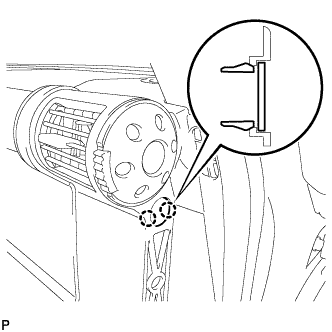
Engage the 4 clips and 2 claws and install the instrument panel register.
Install the bolt and clip.
Engage the 2 claws and install the instrument panel hole cover.
9.
INSTALL INSTRUMENT PANEL LOWER FINISH PANEL SUB-ASSEMBLY RH
Install the connectors to the instrument panel lower finish panel.
Engage the claw and 2 clips and install the instrument panel lower finish panel.
Install the screw <A>.
10.
INSTALL GLOVE COMPARTMENT DOOR ASSEMBLY
Engage the claw and install the glove compartment door stopper.
11.
INSTALL COMBINATION METER ASSEMBLY
Connect the 2 connectors and the clamp.
Install the combination meter assembly with the 4 screws.
Torque:
7.0 N*m{
71 kgf*cm
, 62 in.*lbf
}
12.
INSTALL INSTRUMENT CLUSTER LOWER FINISH PANEL
Connect the connectors.
Engage the 3 clips and the 4 claws and install the instrument cluster lower finish panel.
13.
INSTALL INSTRUMENT LOWER PANEL
Install the lower instrument panel with the 4 <E> bolts.
14.
INSTALL INSTRUMENT PANEL LOWER FINISH PANEL SUB-ASSEMBLY LH
Engage the 5 clips and claw and install the lower instrument panel finish panel.
Install the 2 <E> bolts.
15.
INSTALL HOOD LOCK CONTROL LEVER SUB-ASSEMBLY
Engage the 3 claws and install the hood lock control lever.
16.
INSTALL INSTRUMENT PANEL REGISTER ASSEMBLY LH
Engage the 4 clips and 2 claws and install the instrument panel register.
17.
INSTALL INSTRUMENT LOWER COVER SUB-ASSEMBLY
Engage the 3 clips and 2 claws and install the instrument lower cover.
Install the 2 <E> bolts and 2 clips.
18.
INSTALL FRONT CONSOLE BOX UPPER PANEL GARNISH
Slide the console upper panel garnish toward the front of the vehicle and engage guide. Engage the claw and clip and install the console upper panel garnish.
19.
INSTALL FRONT CONSOLE BOX
Engage the 5 guides and install the front console box.
Install the 4 <H> bolts.
20.
INSTALL FRONT CONSOLE BOX BOTTOM MAT
Install the box bottom mat.
21.
INSTALL FRONT CONSOLE BOX UPPER PANEL SUB-ASSEMBLY
Engage the 3 guides and 5 clips and install the console upper rear panel.
22.
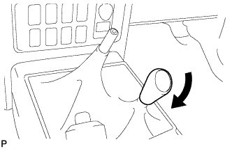
INSTALL SHIFT LEVER KNOB SUB-ASSEMBLY (for 4WD)
Install the shift lever knob.
23.
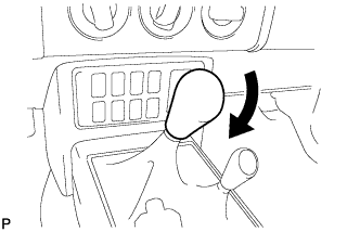
INSTALL SHIFT LEVER KNOB SUB-ASSEMBLY (for Manual Transmission)
Install the shift lever knob.
24.
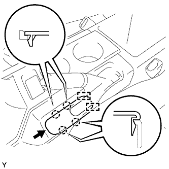
INSTALL PARKING BRAKE HOLE COVER SUB-ASSEMBLY
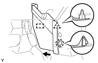
Slide the parking brake hole cover toward the rear of the vehicle and engage the 2 guides. Engage the 4 claws and install the parking brake hole cover.
25.
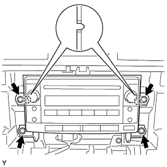
INSTALL RADIO RECEIVER ASSEMBLY
Connect the connectors. Align the 2 bosses of the radio bracket with the hole in the instrument panel and install the radio receiver with the 4 bolts.
Torque:
2.5 N*m{
25 kgf*cm
, 22 in.*lbf
}
26.
INSTALL INTEGRATION CONTROL PANEL ASSEMBLY
Connect the 3 connectors.
Engage the 4 clips and install the integration control panel assembly.
Install the 2 screws.
27.
INSTALL INSTRUMENT PANEL GARNISH LH
Engage the 3 clips and install the instrument panel garnish.
Install the screw <G>.
28.
INSTALL INSTRUMENT PANEL GARNISH RH
Engage the 3 clips and install the instrument panel garnish.
Install the screw <G>.
29.
INSTALL ASSIST GRIP RETAINER RH
Install the assist grip retainer with the 2 bolts.
Torque:
29 N*m{
296 kgf*cm
, 21 ft.*lbf
}
30.
INSTALL ASSIST GRIP RETAINER LH
HINT:
Use the same procedure as for the RH side.
31.
INSTALL FRONT PILLAR GARNISH RH
w/ Assist Grip:
Engage the guide and the 2 clips and install the front pillar garnish.
w/o Assist Grip:
Engage the guide and the 2 clips and install the front pillar garnish.
Install the bolt.
Engage the claw and close the cover.
32.
INSTALL FRONT PILLAR GARNISH LH
HINT:
Use the same procedure as for the RH side.
33.
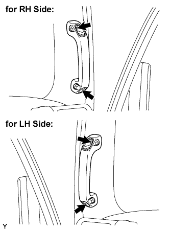
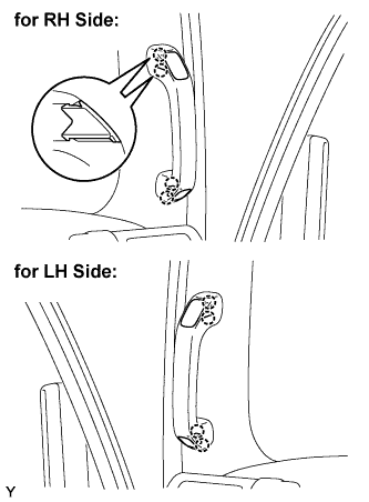
INSTALL ASSIST GRIP ASSEMBLY
HINT:
Use the same procedure to install all the assist grips.
Install the assist grip with the 2 screws.
34.
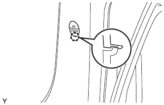
INSTALL ASSIST GRIP PLUG
HINT:
Use the same procedure to install all the assist grip plugs.
Engage the 2 claws and install the assist grip plug.
35.
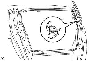
INSTALL FRONT DOOR OPENING TRIM WEATHERSTRIP RH
Install the front door opening trim weatherstrip.
36.
INSTALL FRONT DOOR OPENING TRIM WEATHERSTRIP LH
HINT:
Use the same procedure as for the RH side.
37.
INSTALL COWL SIDE TRIM BOARD RH
Engage the 2 claws and install the cowl side trim board.
Install the clip.
38.
INSTALL COWL SIDE TRIM BOARD LH
HINT:
Use the same procedure as for the RH side.
39.
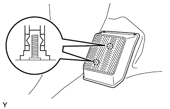
INSTALL FOOTREST CLIP
HINT:
Use the same procedure for both sides.
Engage the 2 claws and install the footrest clip.
40.
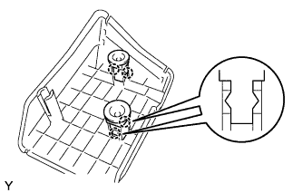
INSTALL FRONT FLOOR FOOTREST
Engage the 2 studs and install the front floor footrest.
41.
INSTALL FRONT DOOR SCUFF PLATE RH
Engage the 14 claws and install the door scuff plate.
42.
INSTALL FRONT DOOR SCUFF PLATE LH
HINT:
Use the same procedure as for the RH side.
43.
CONNECT CABLE TO NEGATIVE BATTERY TERMINAL
Torque:
3.9 N*m{
40 kgf*cm
, 35 in.*lbf
}
44.
INSPECT SRS WARNING LIGHT
(Click here )