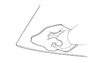
Clean the outer circumference of the glass with a non-residue solvent.
NOTICE:
Do not touch the glass surface after cleaning it.
Even if using a new glass, clean the glass with a non-residue solvent.
2.
CLEAN VEHICLE BODY
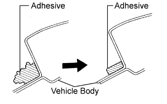
Clean and shape the contact surface of the vehicle body.
Using a knife, cut away any rough adhesive on the contact surface of the vehicle body to ensure the appropriate surface shape.
NOTICE:
Do not damage the vehicle body.
HINT:
Leave as much adhesive on the vehicle body as possible.
Clean the contact surface of the vehicle body with a shop rag or piece of cloth saturated with cleaner.
HINT:
Clean the vehicle body even if all the adhesive has been removed.
3.
INSTALL REAR DOOR GLASS
HINT:
Use the same procedure as for the LH side (Click here).
4.
INSTALL ACCESS DOOR GLASS OUTER WEATHERSTRIP
HINT:
Use the same procedure as for the LH side (Click here).
5.
INSTALL REAR DOOR OUTSIDE MOULDING SUB-ASSEMBLY
HINT:
Use the same procedure as for the LH side (Click here).
6.
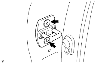
INSTALL ACCESS PANEL LOWER LOCK STOP
Using "Torx" socket wrench T40, install the access panel lower lock stop with the 2 screws.
Torque:
23 N*m{
235 kgf*cm
, 17 ft.*lbf
}
7.
INSTALL DOOR TRIM PAD (w/ Door Trim Pad)
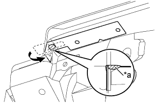
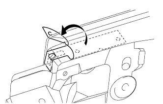
Clean the installation surface on the door panel side.
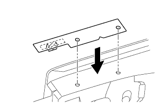
Align the two holes of the application tape with the two holes of the door panel, and adhere a new door trim pad to the upper surface of the door panel.
Following the shape of the door panel, adhere the door trim pad to the side surface of the door panel.
NOTICE:
To prevent the tape from sagging, keep the tape pulled taut while adhering it to the door panel.
Text in Illustration
*a
Sponge Portion
As shown in the illustration, remove the application tape.
Press on the tape firmly to fully adhere it to the door panel.
8.
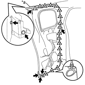
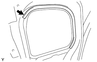
INSTALL ACCESS PANEL WEATHERSTRIP
Clean the installation surface on the door panel side.
Align the corner portion of a new access panel weatherstrip with the door panel.
Text in Illustration
*a
Corner Portion
Engage the 19 clips and install the access panel weatherstrip.
Install the 7 clips.
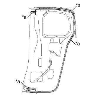
Install the 4 pieces of double-sided tape.
HINT:
When installing the double-sided tape, peel off the backing paper from the tab side.
Text in Illustration
*a
Double-sided Tape
9.
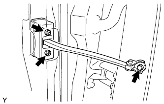
INSTALL ACCESS PANEL CHECK ASSEMBLY
Apply MP grease to the sliding areas of the access panel check.
Install the access panel check onto the door panel with the 2 nuts.
Torque:
5.5 N*m{
56 kgf*cm
, 49 in.*lbf
}
Apply adhesive to the threads of the bolt.
Adhesive:
Toyota Genuine Adhesive 1324, Three Bond 1324 or the equivalent.
Install the access panel check onto the body panel with the bolt.
Torque:
30 N*m{
306 kgf*cm
, 22 ft.*lbf
}
10.
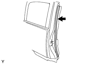
INSTALL REAR DOOR OPENING TRIM
Install the rear door opening trim.
11.
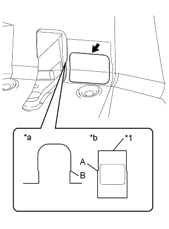
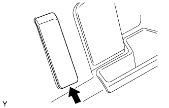
INSTALL REAR DOOR PANEL PROTECTOR
Using a piece of cloth, clean the attachment surface.
Align the edge A of the application tape with the edge B of the rear door panel, and install a new rear door panel protector.
Text in Illustration
*1
Application Tape
*a
Rear Door Panel
*b
Rear Door Panel Protector
NOTICE:
Do not remove the application tape until after the rear door panel protector has been installed.
Securely install the rear door panel protector, taking care to prevent wrinkles and air bubbles.
HINT:
Peel off the backing paper from the rear door panel protector before installing the rear door panel protector.
Remove the application tape from the rear door panel protector.
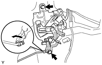
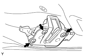
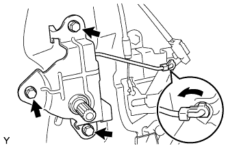
Install the access panel inside handle with the 3 bolts.
Torque:
12 N*m{
122 kgf*cm
, 9 ft.*lbf
}
Connect the rod.
19.
INSTALL FRONT SHOULDER BELT ANCHOR ADJUSTER ASSEMBLY
Insert the hook into the body hole and provisionally install the shoulder belt anchor adjuster with the 2 bolts.
Tighten the upper bolt and then the lower bolt.
Torque:
42 N*m{
428 kgf*cm
, 31 ft.*lbf
}
20.
INSTALL FRONT SEAT OUTER BELT ASSEMBLY
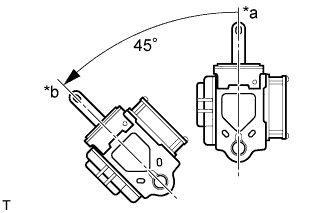
Check the angle of inclination required to lock the retractor.
Text in Illustration
*a
Unlock
*b
Lock
Gently incline the retractor from its initial position. Check that the belt does not lock when the retractor is inclined 15° or less in any direction. Also, check that the belt locks when the inclination of the retractor is 45° or more.
NOTICE:
Do not disassemble the retractor.
If the operation is not as specified, replace the front seat outer belt.
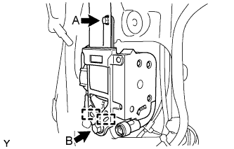
Hook the lower stay of the retractor onto the 2 body hooks and provisionally install the retractor with the 2 bolts.
Tighten bolt A and then bolt B.
Torque:
8.5 N*m{
87 kgf*cm
, 75 in.*lbf
}
for bolt A
42 N*m{
428 kgf*cm
, 31 ft.*lbf
}
for bolt B
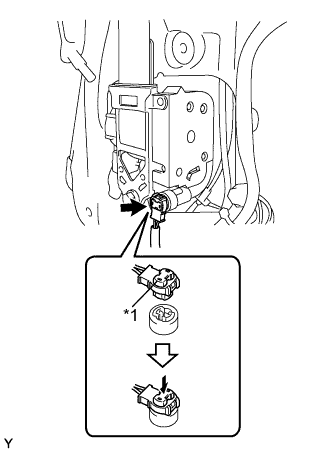
Connect the pretensioner connector.
Text in Illustration
*1
Locking Button
Lock the locking button of the pretensioner connector.
NOTICE:
Securely lock the locking button.
Install the through anchor with the nut.
Torque:
42 N*m{
428 kgf*cm
, 31 ft.*lbf
}
Make sure that the shoulder anchor rotates smoothly.
Check that the ELR locks.
NOTICE:
Perform the check with the front seat outer belt installed.
With the belt installed, check that the belt locks when it is pulled out quickly. If the operation is not as specified, replace the front seat outer belt.
21.
INSTALL CENTER PILLAR UPPER GARNISH
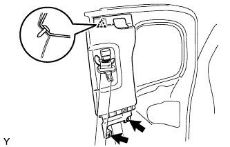
Engage the 2 clips and install the center pillar upper garnish.
Install the 2 screws.
Install the clip.
22.
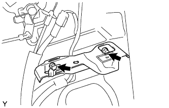
INSTALL REAR DOOR TRIM BRACKET
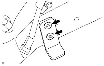
Install the rear door trim bracket with the 2 screws.
23.
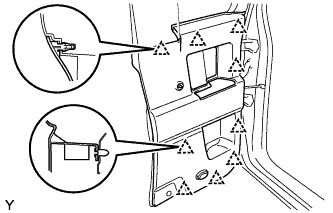
INSTALL REAR DOOR TRIM BOARD SUB-ASSEMBLY
Engage the 9 clips and install the rear door trim board.
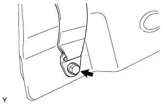
Install the front seat belt outer (floor side) with the bolt.
Torque:
42 N*m{
428 kgf*cm
, 31 ft.*lbf
}
24.
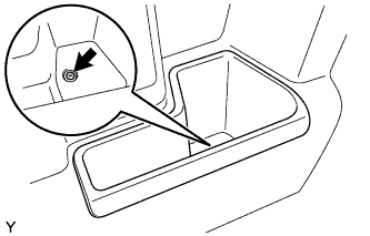
INSTALL NO. 1 CUP HOLDER
Install the No. 1 cup holder with the screw.
25.
INSTALL REAR DOOR INSIDE HANDLE SUB-ASSEMBLY
Install the rear door inside handle with the snap ring onto the access panel inside handle.
26.
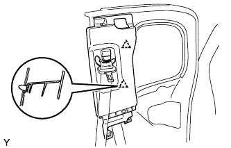
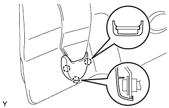
INSTALL LAP BELT OUTER ANCHOR COVER
Engage the 3 claws and install the lap belt outer anchor cover.