Versions by build date: Jul 2007 – Jul 2009from Aug 2009
INSPECT CAMSHAFTS
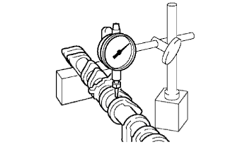
Inspect the camshaft for runout.
Place the camshaft on V-blocks.
Using a dial indicator, measure the circle runout at the center journal.
Maximum runout:
0.06 mm (0.0024 in.)
If the circle runout is greater than the maximum, replace the camshaft.
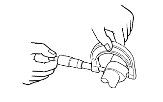
Inspect the cam lobes.
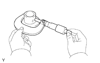
Using a micrometer, measure the cam lobe height.
Standard cam lobe height:
Intake:
44.168 to 44.268 mm (1.7389 to 1.7428 in.)
Exhaust:
44.580 to 44.680 mm (1.7551 to 1.7591 in.)
Minimum cam lobe height:
Intake:
44.018 mm (1.7330 in.)
Exhaust:
44.430 mm (1.7492 in.)
If the cam lobe height is less than the minimum, replace the camshaft.
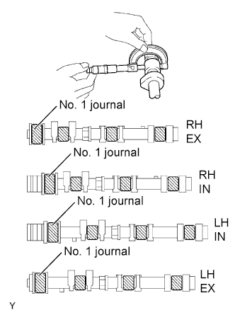
Inspect the camshaft journals.
Using a micrometer, measure the journal diameter.
No. 1 journal diameter:
35.971 to 35.985 mm (1.4162 to 1.4167 in.)
Other journal diameters:
22.959 to 22.975 mm (0.9039 to 0.9045 in.)
If the journal diameter is not as specified, check the oil clearance.
INSPECT CAMSHAFT TIMING GEAR ASSEMBLY
Fix the intake camshaft in a vise.
NOTICE:
Be careful not to damage the camshaft.
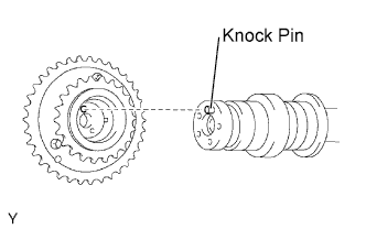
Align the knock pin hole in the camshaft timing gear assembly with the knock pin of the camshaft, and install the camshaft timing gear assembly with the bolt.
Torque:
100 N*m{
1020 kgf*cm
, 74 ft.*lbf
}
Confirm that the camshaft timing gear assembly is locked.
Release that lock pin.
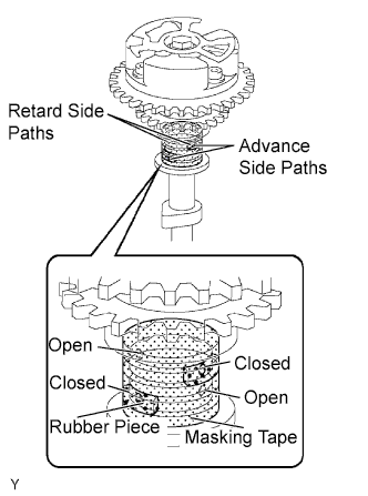
Cover the 4 oil paths of the cam journal with masking tape as shown in the illustration.
HINT:
One of the 2 grooves on the cam journal is for the retard side path (upper) and the other is for the advance side path (lower). Each groove has 2 oil paths. Plug one of the oil paths for each groove with a piece of rubber before wrapping the cam journal with tape.
Puncture the tape covering the advance oil path and retard oil path on the opposite side of the groove as shown in the illustration.
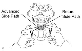
Apply compressed air at 200 kPa (2.0 kgf/cm2) into the 2 broken paths (the advance side path and the retard side path).
NOTICE:
Cover the paths with a shop rag or piece of cloth to avoid oil splashes.
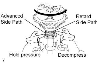
Confirm that the camshaft timing gear assembly rotates in the timing advance direction when reducing the compressed air on the timing retard path.
HINT:
When the lock pin is released, the camshaft timing gear rotates in the advance direction.
When the camshaft timing gear comes to the most advanced position, release the compressed air on the timing retard side path, and release that on the timing advance side path.
NOTICE:
Camshaft timing assembly gear occasionally shifts to the retard side abruptly if the air compression on the advanced side path is released first. This often causes breakage of the lock pin.
Check the smooth revolution.
Rotate the camshaft timing gear several times within the movable range except for the most retarded position and check it rotates smoothly.
Standard:
Moves smoothly in a range of about 31°
NOTICE:
Be sure to perform this check by hand, instead of using compressed air.
Check that the lock is in the most retarded position.
Confirm that the camshaft timing gear assembly is locked in the most retarded position.
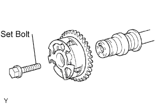
Remove the set bolt, then remove the camshaft timing gear assembly.
NOTICE:
Do not remove the other 3 bolts.
INSPECT CYLINDER HEAD SET BOLT
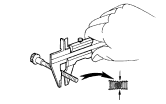
Using vernier calipers, measure the outer diameter of the cylinder head set bolt thread.
Standard outer diameter:
10.85 to 11.00 mm (0.4272 to 0.4331 in.)
Minimum outer diameter:
10.7 mm (0.421 in.)
If the outer diameter is less than the minimum, replace the cylinder head set bolt.
INSPECT CHAIN SUB-ASSEMBLY
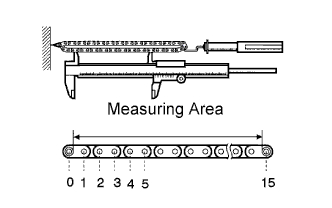
Using a spring scale, apply 147 N (15.0 kgf, 33.1 lbf) to the chain and measure the length.
Maximum chain length:
146.8 mm (5.780 in.)
NOTICE:
Measure the length in at least 3 places and calculate the average length.
If the chain length is greater than the maximum, replace the chain.
INSPECT NO. 2 CHAIN SUB-ASSEMBLY
Using a spring scale, apply 147 N (15.0 kgf, 33.1 lbf) to the chain and measure the length.
Maximum chain length:
146.8 mm (5.780 in.)
NOTICE:
Measure the length in at least 3 places and calculate the average length.
If the chain length is greater than the maximum, replace the chain.
INSPECT CAMSHAFT TIMING GEAR ASSEMBLY
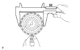
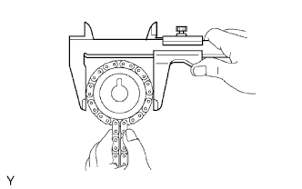
Wrap the chain sub-assembly around the larger gear of the timing gear assembly.
Using vernier calipers, measure the timing gear with the chain wrapped.
Minimum gear diameter (with chain):
115.5 mm (4.547 in.)
NOTICE:
The vernier calipers must be in contact with the chain rollers when measuring.
If the gear diameter is less than the minimum, replace the chain sub-assembly and the camshaft timing gear assembly.
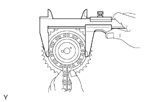
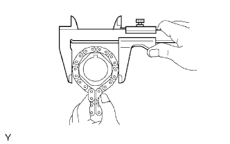
Wrap the No. 2 chain around the smaller gear of timing gear assembly.
Using vernier calipers, measure the timing gear with the chain wrapped.
Minimum gear diameter (with chain):
73.1 mm (2.878 in.)
NOTICE:
The vernier calipers must be in contact the chain rollers when measuring.
If the gear diameter is less than the minimum, replace the No. 2 chain and the camshaft timing gear assembly.
INSPECT CAMSHAFT TIMING GEAR OR SPROCKET
Wrap the No. 2 chain around the timing gear.
Using vernier calipers, measure the camshaft timing gear diameter with the chain wrapped.
Minimum gear diameter (with chain):
73.1 mm (2.878 in.)
NOTICE:
The vernier calipers must be in contact the chain rollers when measuring.
If the gear diameter is less than the minimum, replace the No. 2 chain and camshaft timing gear.
INSPECT CRANKSHAFT TIMING GEAR OR SPROCKET
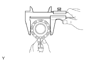
Wrap the chain sub-assembly around the timing gear.
Using vernier calipers, measure the timing gear diameter with the chain wrapped.
Minimum gear diameter (with chain):
61.0 mm (2.402 in.)
NOTICE:
The vernier calipers must be in contact with the chain rollers when measuring.
If the gear diameter is less than the minimum, replace the chain sub-assembly and the crankshaft timing gear.
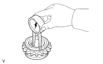
INSPECT IDLE SPROCKET ASSEMBLY
Wrap the chain sub-assembly around the idle sprocket.
Using vernier calipers, measure the idle sprocket with the chain wrapped.
Minimum gear diameter (with chain):
61.0 mm (2.402 in.)
NOTICE:
The vernier calipers must be in contact with the chain rollers when measuring.
If the gear diameter is less than the minimum, replace the chain sub-assembly and idle sprocket.
INSPECT NO. 1 IDLE GEAR SHAFT
Using a micrometer, measure the idle gear shaft diameter.
Idle gear shaft diameter:
22.987 to 23.000 mm (0.9050 to 0.9055 in.)
If the result is not as specified, replace the idle gear shaft.
Using a caliper gauge, measure the internal diameter of the idle gear.
Idle gear internal diameter:
23.02 to 23.03 mm (0.9063 to 0.9067 in.)
If the result is not as specified, replace the idle gear.
Subtract the idle gear shaft diameter measurement from the idle gear internal diameter measurement.
Standard oil clearance:
0.020 to 0.043 mm (0.0008 to 0.0017 in.)
Maximum oil clearance:
0.093 mm (0.0037 in.)
If the oil clearance is greater than the maximum, replace the idle gear or gear shaft.
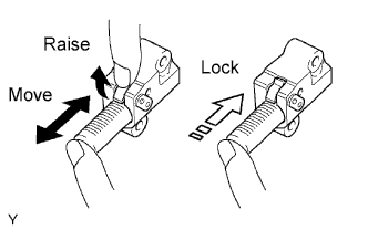
INSPECT NO. 1 CHAIN TENSIONER ASSEMBLY
Check that the plunger moves smoothly when the ratchet pawl is raised with finger.
Release the ratchet pawl, then check that the plunger is locked in place by the ratchet pawl and does not move when pushing it with finger. If the results are not as specified, replace the No. 1 chain tensioner assembly.
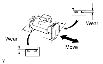
INSPECT NO. 2 CHAIN TENSIONER ASSEMBLY
Check that the plunger moves smoothly.
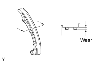
Measure the wear of the chain tensioner slipper.
Maximum wear:
1.0 mm (0.039 in.)
If the wear is greater than the maximum, replace chain tensioner No. 2.
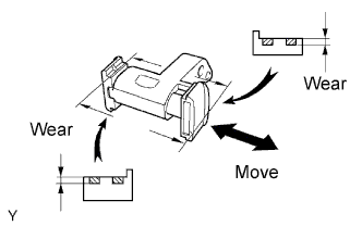
INSPECT NO. 3 CHAIN TENSIONER ASSEMBLY
Check that the plunger moves smoothly.
Measure the wear of the chain tensioner slipper.
Maximum wear:
1.0 mm (0.039 in.)
If the wear is greater than the maximum, replace chain tensioner No. 3.
INSPECT CHAIN TENSIONER SLIPPER
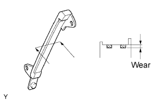
Measure the wear of the tensioner slipper.
Maximum wear:
1.0 mm (0.039 in.)
If the thickness is greater than the maximum, replace the tensioner slipper.
INSPECT NO. 1 CHAIN VIBRATION DAMPER
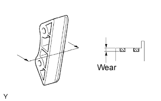
Measure the wear of the vibration damper No. 1.
Maximum wear:
1.0 mm (0.039 in.)
If the thickness is greater than the maximum, replace vibration damper No. 1.
INSPECT NO. 2 CHAIN VIBRATION DAMPER
Measure the wear of the vibration damper No. 2 .
Maximum wear:
1.0 mm (0.039 in.)
If the thickness is greater than the maximum, replace vibration damper No. 2.
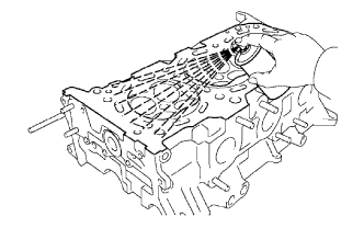
CLEAN CYLINDER HEAD SUB-ASSEMBLY
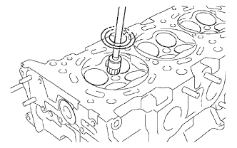
Using a gasket scraper, remove all the gasket material from the cylinder block contact surface.
NOTICE:
Be careful not to scratch the cylinder block contact surface.
Using a wire brush, remove all the carbon from the combustion chambers.
NOTICE:
Be careful not to scratch the combustion chambers.
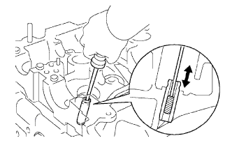
Using a valve guide bushing brush and solvent, clean all the valve guide bushes.
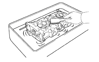
Using a soft brush and solvent, thoroughly clean the cylinder head.
INSPECT CYLINDER HEAD SUB-ASSEMBLY
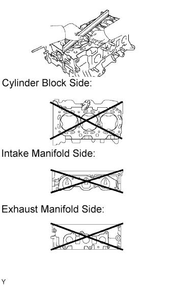
Inspect the cylinder head for warpage.
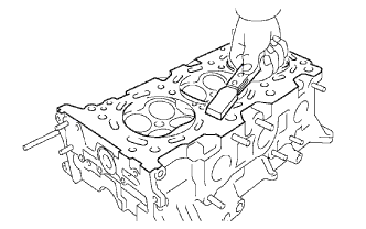
Using a precision straight edge and feeler gauge, measure the warpage on the cylinder block side and the intake and exhaust sides.
Maximum warpage:
0.10 mm (0.0039 in.)
If the warpage is greater than the maximum, replace the cylinder head.
Inspect the cylinder head for cracks.
Using a dye penetrant, check the combustion chamber, intake ports, exhaust ports and cylinder block surface for cracks. If cracked, replace the cylinder head.
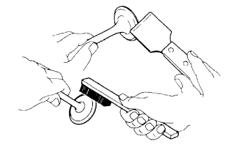
CLEAN VALVE
Using a gasket scraper, chip off any carbon from the valve head.
Using a wire brush, thoroughly clean the valve.
INSPECT VALVE
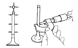
Inspect the valve stem diameter.
Using a micrometer, measure the diameter of the valve stem.
Valve stem diameter:
Valve Stem
Specification
Intake
5.470 to 5.485 mm (0.2154 to 0.2159 in.)
Exhaust
5.465 to 5.480 mm (0.2152 to 0.2158 in.)
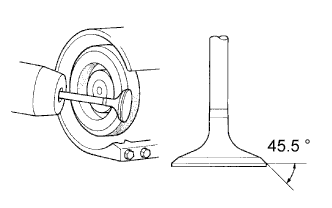
Inspect the valve face angle.
Grind the valve enough to remove any pits and carbon.
Check that the valve is ground to the correct valve face angle.
Valve face angle:
45.5°
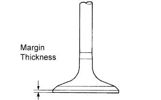
Inspect the valve head margin thickness.
Using vernier calipers, check the valve head margin thickness.
Standard margin thickness:
1.0 mm (0.039 in.)
Minimum margin thickness:
0.5 mm (0.020 in.)
If the margin thickness is less than the minimum, replace the valve.
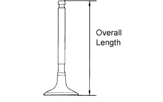
Inspect the overall length.
Using vernier calipers, check the overall length.
Standard overall length:
Valve
Specification
Intake
106.95 mm (4.2106 in.)
Exhaust
105.80 mm (4.1654 in.)
Minimum overall length:
Valve
Specification
Intake
106.70 mm (4.2008 in.)
Exhaust
105.55 mm (4.1555 in.)
If the overall length is less than the minimum, replace the valve.
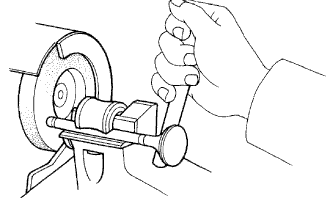
Inspect the valve stem tip.
Check the surface of the valve stem tip for wear.
NOTICE:
Do not grind to less than the minimum length.
If the valve stem tip is worn, resurface the tip with a grinder or replace the valve.
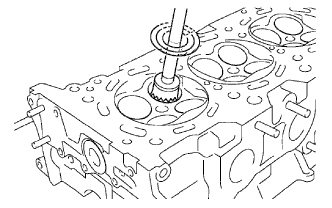
CLEAN VALVE SEAT
Using a 45° carbide cutter, resurface the valve seats.
Clean the valve seats.
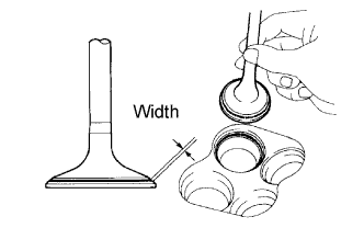
INSPECT VALVE SEAT
Apply a light coat of prussian blue to the valve face.
Lightly press the valve against the valve seat.
NOTICE:
Do not rotate the valve.
Check the valve face and seat according to the following procedure.
If blue appears 360° around the face, the valve is concentric. If not, replace the valve.
If the blue appears 360° around the valve seat, the guide and face are concentric. If not, resurface the valve seat.
Check that the seat is in contact with the middle of the valve face with the following width.
Standard width:
1.0 to 1.4 mm (0.039 to 0.055 in.)
INSPECT INNER COMPRESSION SPRING
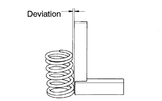
Inspect the deviation.
Using steel squares, measure the deviation of the inner compression spring.
Maximum deviation:
2.0 mm (0.079 in.)
If the deviation is greater than the maximum, replace the inner compression spring.
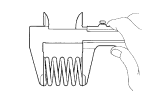
Inspect the free length.
Using vernier calipers, measure the free length of the inner compression spring.
Free length:
47.80 mm (1.8819 in.)
If the free length is not as specified, replace the inner compression spring.
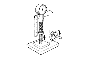
Inspect the tension.
Using a spring tester, measure the tension of the inner compression spring at the specified installed length.
Installed tension:
Installed Length
Specification
33.3 mm (1.311 in.)
186.2 to 205.8 N (19.0 to 21.0 kgf, 41.9 to 46.3 lbf)
If the installed tension is not as specified, replace the inner compression spring.
INSPECT VALVE GUIDE BUSH OIL CLEARANCE
Using a caliper gauge, measure the internal diameter of the valve guide bush.
Inside diameter:
5.51 to 5.53 mm (0.2169 to 0.2177 in.)
Subtract the valve stem diameter measurement from the valve guide bush internal diameter measurement.
Standard oil clearance:
Valve Guide Bush
Specification
Intake
0.025 to 0.060 mm (0.0010 to 0.0024 in.)
Exhaust
0.030 to 0.065 mm (0.0012 to 0.0026 in.)
Maximum oil clearance:
Valve Guide Bush
Specification
Intake
0.08 mm (0.0031 in.)
Exhaust
0.10 mm (0.0039 in..)
If the oil clearance is greater than the maximum, replace the valve and valve guide bush.
INSPECT VALVE LIFTER
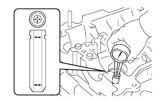
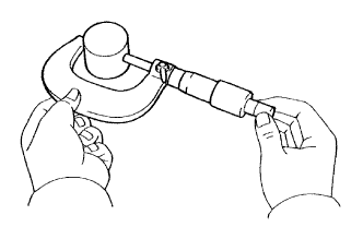
Using a micrometer, measure the valve lifter diameter.
Valve lifter diameter:
30.966 to 30.976 mm (1.2191 to 1.2195 in.)
INSPECT VALVE LIFTER OIL CLEARANCE
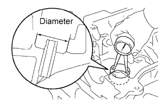
Using a caliper gauge, measure the lifter bore diameter of the cylinder head.
Lifter bore diameter:
31.009 to 31.025 mm (1.2208 to 1.2215 in.)
Subtract the valve lifter diameter measurement (Step 16) from the lifter bore diameter measurement.
Standard oil clearance:
0.033 to 0.059 mm (0.0013 to 0.0023 in.)
Maximum oil clearance:
0.08 mm (0.0031 in.)
If the oil clearance is greater than the maximum, replace the valve lifter. If necessary, replace the cylinder head.
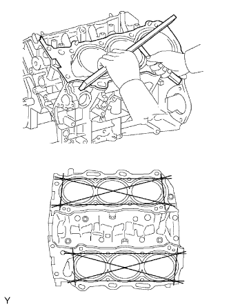
CHECK CYLINDER BLOCK FOR WARPAGE
Using a precision straight edge and feeler gauge, measure the warpage of the contact surface of the cylinder head gasket.
Maximum warpage:
0.05 mm (0.0020 in.)
If the warpage is greater than the maximum, replace the cylinder block.
INSPECT CYLINDER BORE
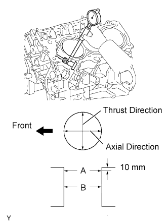
Using a cylinder gauge, measure the cylinder bore diameter at positions A and B in the thrust and axial directions.
Standard diameter:
94.000 to 94.012 mm (3.7008 to 3.7013 in.)
Maximum diameter:
94.132mm (3.7060 in.)
If the average diameter of the 4 positions is greater than the maximum, replace the cylinder block.
INSPECT WITH PISTON SUB-ASSEMBLY
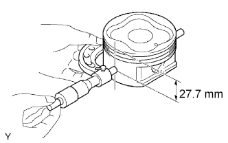
Using a micrometer, measure the piston diameter at right angles to the piston pin center line, 27.7 mm (1.091 in.) from the piston head.
Piston diameter:
93.910 to 93.940 mm (3.6972 to 3.6984 in.)
If the result is not as specified, replace the with piston sub-assembly.
INSPECT PISTON OIL CLEARANCE
Subtract the piston diameter measurement from the cylinder bore diameter measurement.
Standard oil clearance:
0.060 to 0.102 mm (0.0031 to 0.0040 in.)
Maximum oil clearance:
0.13 mm (0.0051 in.)
If the oil clearance is greater than the maximum, replace all the 6 pistons. If necessary, replace the cylinder block.
INSPECT CONNECTING ROD SUB-ASSEMBLY
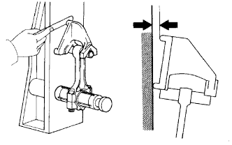
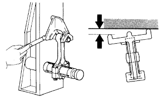
Using a rod aligner and feeler gauge, check the connecting rod alignment.
Check for misalignment.
Maximum misalignment:
0.05 mm (0.0020 in.) per 100 mm (3.94 in.)
If misalignment is greater than the maximum, replace the connecting rod assembly.
Check the twist.
Maximum twist:
0.15 mm (0.0059 in.) per 100 mm (3.94 in.)
If the twist is greater than the maximum, replace the connecting rod assembly.
INSPECT PISTON PIN OIL CLEARANCE
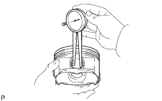
Using a caliper gauge, measure the internal diameter of the piston pin hole.
Piston pin hole internal diameter:
22.001 to 22.010 mm (0.8662 to 0.8665 in.)
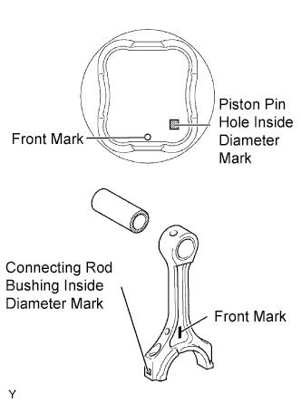
Piston pin hole inside diameter:
Mark
mm (in.)
A
22.001 to 22.004 (0.8662 to 0.8663)
B
22.005 to 22.007 (0.8663 to 0.8664)
C
22.008 to 22.010 (0.8665 to 0.8665)
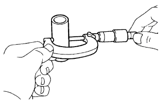
Using a micrometer, measure the piston pin diameter.
Piston pin diameter:
21.997 to 22.006 mm (0.8660 to 0.8664 in.)
Piston pin diameter:
Mark
mm (in.)
A
21.997 to 22.000 (0.8660 to 0.8661)
B
22.001 to 22.003 (0.8661 to 0.8663)
C
22.004 to 22.006 (0.8663 to 0.8664)
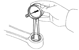
Using a caliper gauge, measure the internal diameter of the connecting rod bushing.
Bushing internal diameter:
22.005 to 22.014 mm (0.8663 to 0.8667 in.)
Bushing internal diameter:
Mark
mm (in.)
A
22.005 to 22.008 (0.8663 to 0.8665)
B
22.009 to 22.011 (0.8665 to 0.8666)
C
22.012 to 22.014 (0.8666 to 0.8667)
Subtract the piston pin diameter measurement from the piton pin hole diameter measurement.
Standard oil clearance:
0.001 to 0.007 mm (0.00004 to 0.00028 in.)
Maximum oil clearance:
0.040 mm (0.0016 in.)
If the oil clearance is greater than the maximum, replace the bushing. If necessary, replace the piston and piston pin together.
Subtract the piston pin diameter measurement from the bushing inside diameter measurement.
Standard oil clearance:
0.005 to 0.011 mm (0.0002 to 0.0004 in.)
Maximum oil clearance:
0.050 mm (0.0020 in.)
If the oil clearance is greater than the maximum, replace the bushing. If necessary, replace the connecting rod and piston pin together.
INSPECT RING GROOVE CLEARANCE
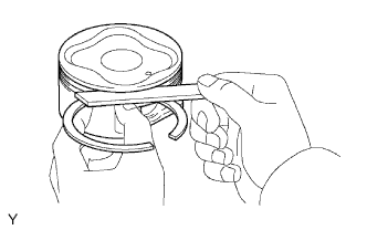
Using a feeler gauge, measure the clearance between a new piston ring and the wall of the ring groove.
Ring groove clearance:
Piston ring
Specification
No. 1
0.02 to 0.07 mm (0.0008 to 0.0028 in.)
No. 2
0.02 to 0.06 mm (0.0008 to 0.0024 in.)
Oil
0.07 to 0.15 mm (0.0028 to 0.0060 in.)
INSPECT PISTON RING END GAP
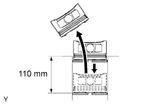
Using a piston, push the piston ring a little beyond the bottom of the ring travel, 110 mm (4.33 in.) from the top of the cylinder block.
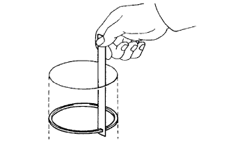
Using a feeler gauge, measure the end gap.
Standard end gap:
Piston ring
Specification
No. 1
0.30 to 0.40 mm (0.0118 to 0.0157 in.)
No. 2
0.40 to 0.50 mm (0.0157 to 0.0197 in.)
Oil (Side rail)
0.10 to 0.40 mm (0.0039 to 0.0157 in.)
Maximum end gap:
Piston ring
Specification
No. 1
1.0 mm (0.039 in.)
No. 2
1.1 mm (0.043 in.)
Oil (Side rail)
1.0 mm (0.039 in.)
INSPECT CONNECTING ROD BOLT
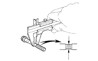
Using vernier calipers, measure the diameter of the elongated portion of the bolt.
Standard diameter:
7.2 to 7.3 mm (0.283 to 0.287 in.)
Minimum diameter:
7.0 mm (0.276 in.)
If the diameter is less than the minimum, replace the bolt.
INSPECT CRANKSHAFT BEARING CAP SET BOLT
Using vernier calipers, measure the diameter of the elongated portion of the bolt.
Standard diameter:
10.0 to 10.2 mm (0.393 to 0.402 in.)
If the diameter is less than the minimum, replace the bolt.
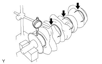
INSPECT CRANKSHAFT
Using a dial indicator and V-blocks, measure the runout as shown in the illustration.
Maximum circle runout:
0.06 mm (0.0024 in.)
If the result is not as specified, replace the crankshaft.
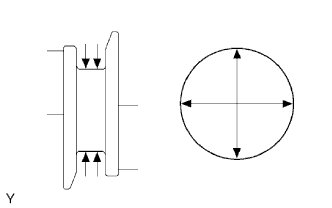
Using a micrometer, measure the diameter of each main journal.
Standard Diameter:
71.988 to 72.000 mm (2.8342 to 2.8346 in.)
If the result is not as specified, replace the crankshaft.
Check each main journal for taper and out-of-roundness as shown.
Maximum taper and out-of-roundness:
0.02 mm (0.0008 in.)
If the result is not as specified, replace the crankshaft.
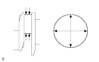
Using a micrometer, measure the diameter of each crank pin.
Standard diameter:
55.992 to 56.000 mm (2.2044 to 2.2047 in.)
If the result is not as specified, replace the crankshaft.
Check each crank pin for taper and out-of-roundness as shown.
Maximum taper and out-of-roundness:
0.02 mm (0.0008 in.)
If the result is not as specified, replace the crankshaft.