TERMINALS OF ECU
System information · Vehicles built Aug 2012 – Oct 2012
Versions by build date: Jul 2007 – Jul 2009 Aug 2009 – Oct 2010 Nov 2010 – Jul 2011 Aug 2011 – Jul 2012 Aug 2012 – Oct 2012 Nov 2012 – Jul 2014 from Aug 2014
| COMBINATION METER ASSEMBLY |
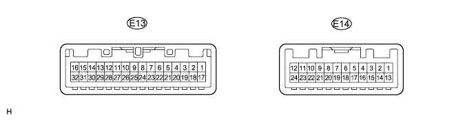

Disconnect the E13 combination meter assembly connector.
Measure the voltage and resistance of the wire harness side connector.
If the result is not as specified, there may be a malfunction in the wire harness.Terminal No. (Symbol)
Wiring Color
Terminal Description
Condition
Specified Condition
E13-1 (B) - Body ground
R - Body ground
Battery
Always
11 to 14 V
E13-2 (IG+) - Body ground
R-L - Body ground
Ignition switch signal
Ignition switch off → ON
Below 1 V → 11 to 14 V
E13-21 (ES) - Body ground
W-B - Body ground
Ground
Always
Below 1 Ω
Disconnect the E14 combination meter assembly connector.
Measure the voltage, resistance and check for pulse of the wire harness side connector.
Terminal No. (Symbol)
Wiring Color
Terminal Description
Condition
Specified Condition
E13-5 (E3) - Body ground
Y-B - Body ground
Fuel level signal
Ignition switch ON
11 to 14 V
E13-7 (WRNP) - Body ground
LG - Body ground
Passenger side seat belt warning light signal (Output)
Ignition switch ON
Front passenger seat is occupied and its seat belt is unfastened
11 to 14 V → Below 1 V
Ignition switch ON
Front passenger seat is occupied and its seat belt is fastened
Below 1 V
E13-8 (L) - Body ground
G-Y - Body ground
Seat belt condition signal (Driver side)
D-BELT indicator light ON → OFF
Below 1 V → 11 to 14 V
E13-9 (KSW) - Body ground
V-G - Body ground
Key switch condition signal
Key inserted → removed
Below 1 V → 11 to 14 V
E13-10 (PBKL) - Body ground
L-R - Body ground
Front seat inner belt signal (Front passenger side)
Ignition switch ON
Front seat belt is unfastened or fastened (Front passenger side)
Pulse generation
E13-11 (ILL-)*2 - Body ground
BR-W - Body ground
Light control rheostat signal
Ignition switch off → ON
Pulse generation
(See waveform 1)
E13-13 (SI) - Body ground
GR-R - Body ground
Vehicle speed signal (Input)
Driving at approx. 20 km/h (12 mph)
Pulse generation
(See waveform 2)
E13-14 (+S) - Body ground
V-R - Body ground
Vehicle speed signal (Output)
Ignition switch ON and wheel turning slowly
Pulse generation
(See waveform 2)
E13-16 (L) - Body ground
V-W - Body ground
Fuel level signal
Ignition switch ON
11 to 14 V
E13-18 (B) - Body ground
P - Body ground
Turn signal RH signal
Ignition switch ON
Turn signal RH indicator light OFF → ON → OFF
Below 1 V → 11 to 14 V → Below 1 V
E13-20 (B) - Body ground
L-W - Body ground
Turn signal LH signal
Ignition switch ON
Turn signal LH indicator light OFF → ON → OFF
Below 1 V → 11 to 14 V → Below 1 V
E13-23 (SW) - Body ground
V-Y - Body ground
All door condition signal
All doors open → closed
Below 1 V → 11 to 14 V
E13-26 (+) - Body ground
R-W - Body ground
HEAD light signal
Light control switch OFF → ON
Below 1 V → 11 to 14 V
E13-29 (DOOR) - Body ground
W-L - Body ground
Driver side door open
Driver side door open → closed
Below 1 V → 11 to 14 V
E13-30 (+)*4 - Body ground
LG-R - Body ground
Rear fog light signal
Light control switch ON
Rear fog light switch OFF → ON
Below 1 V → 11 to 14 V
E14-1 (RRSW)*5 - Body ground
L-Y - Body ground
Rear differential lock signal
Rear differential lock indicator light ON → OFF
Below 1 V → 11 to 14 V
E14-2 (SW)*1 - Body ground
GR - Body ground
4WD signal
Center differential lock indicator light OFF → ON
Below 1 V → 11 to 14 V
E14-2 (SW)*3 - Body ground
R-L - Body ground
4WD signal
4WD indicator OFF → ON
Below 1 V → 11 to 14 V
E14-3 (CHG-) - Body ground
GR - Body ground
Charge signal
Ignition switch ON → off
11 to 14 V → Below 1 V
E14-7 (CHK) - Body ground
R-B - Body ground
Check engine warning light signal
Check engine warning light signal ON → OFF
Below 1 V → 11 to 14 V
E14-9 (CANL) - Body ground
W - Body ground
CAN communication signal
Ignition switch off
200 Ω or higher
E14-10 (CANH) - Body ground
R - Body ground
CAN communication signal
Ignition switch off
200 Ω or higher
E14-12 (S) - Body ground
LG-B - Body ground
Oil pressure signal
Oil pressure warning light ON → OFF
Below 1 V → 11 to 14 V
E14-13 (ILL+) - Body ground
G - Body ground
Taillight signal
Light control switch OFF → ON
Below 1 V → 11 to 14 V
E14-14 (L)*3 - Body ground
B-L - Body ground
A/T shift position signal (L)
A/T L indicator OFF → ON
Below 1 V → 11 to 14 V
E14-15 (2)*3 - Body ground
P-L - Body ground
A/T shift position signal (2)
A/T 2 indicator OFF → ON
Below 1 V → 11 to 14 V
E14-16 (3)*3 - Body ground
W-R - Body ground
A/T shift position signal (3)
A/T 3 indicator OFF → ON
Below 1 V → 11 to 14 V
E14-17 (4)*3 - Body ground
L - Body ground
A/T shift position signal (4)
A/T 4 indicator OFF → ON
Below 1 V → 11 to 14 V
E14-18 (D)*3 - Body ground
R-G - Body ground
A/T shift position signal (D)
A/T D indicator OFF → ON
Below 1 V → 11 to 14 V
E14-19 (N)*3 - Body ground
G-W - Body ground
A/T shift position signal (N)
A/T N indicator OFF → ON
Below 1 V → 11 to 14 V
E14-20 (R)*1 - Body ground
R-Y - Body ground
M/T shift position signal (R)
M/T shift warning buzzer OFF → ON
Below 1 V → 11 to 14 V
E14-20 (R)*3 - Body ground
R-Y - Body ground
A/T shift position signal (R)
A/T R indicator OFF → ON
Below 1 V → 11 to 14 V
E14-21 (P)*3 - Body ground
Y-B - Body ground
A/T shift position signal (P)
A/T P indicator OFF → ON
Below 1 V → 11 to 14 V
E14-22 (A/T3)*3 - Body ground
B-R - Body ground
Transfer indicator switch neutral position signal
A/T P indicator OFF → ON
Below 1 V → 11 to 14 V
E14-24 (RHCL)*6,*7 - Body ground
W-G - Body ground
Ground (Illumination ground)
Always
Below 1 V
- *1: for Manual Transmission
- *2: w/ Light Control Rheostat
- *3: for Automatic Transmission
- *4: w/ Rear Fog Light
- *5: w/ Rear Differential Lock
- *6: w/ CRAWL
- *7: w/o Light Control Rheostat
- HINT:
- If the result is not as specified, the combination meter assembly may be malfunctioning.
Waveform 1: Using an oscilloscope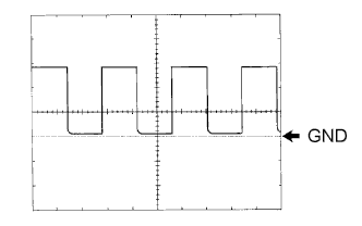
Terminal Connections
E13-11 (ILL-) - Body Ground
Tool Setting
5 V/DIV., 50 ms/DIV.
Condition
Ignition switch ON
Waveform 2: Using an oscilloscope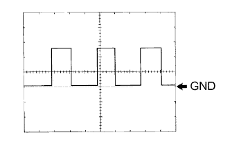
Terminal Connections
E13-13 (SI) - Body Ground
E13-14 (+S) - Body Ground
Tool Setting
5 V/DIV., 20 ms/DIV.
Condition
Driving at approximately 20 km/h (12 mph)
- HINT:
- As the vehicle speed increases, the cycle of the signal waveform narrows.
- *1: for Manual Transmission
| ACCESSORY METER ASSEMBLY |

Disconnect the F1 accessory meter assembly connector.
Measure the voltage and resistance of the wire harness side connector.
Terminal No. (Symbol)
Wiring Color
Terminal Description
Condition
Specified Condition
F1-1 (+B) - Body ground
R - Body ground
Battery
Always
11 to 14 V
F1-2 (ACC) - Body ground
GR - Body ground
ACC
Ignition switch off → ACC
Below 1 V → 11 to 14 V
F1-3 (IG+) - Body ground
Y-R - Body ground
Ignition switch signal
Ignition switch off → ON
Below 1 V → 11 to 14 V
F1-4 (DMIN) - Body ground
R-L - Body ground
Air conditioning amplifier signal
Ignition switch off → ON
Below 1 V → 11 to 14 V
F1-6 (ILL+) - Body ground
G - Body ground
Taillight signal
Light control switch OFF → ON
Below 1 V → 11 to 14 V
F1-7 (ILL-) - Body ground
BR-W - Body ground
Light control rheostat signal
Ignition switch off → ON
Pulse generation
(See waveform 1)
F1-8 (SI) - Body ground
V-R - Body ground
Combination meter signal
Driving at approx. 5 km/h (3.1 mph)
1 V → 9 V → 1 V
Pulse generation
(See waveform 2)
F1-9 (E) - Body ground
W-B - Body ground
Ground
Always
Below 1 Ω
- HINT:
- If the result is not as specified, the accessory meter assembly may be malfunctioning.
Waveform 1: Using an oscilloscope
Terminal Connections
F1-7 (ILL-) -Body Ground
Tool Setting
5 V/DIV., 50 ms/DIV.
Condition
Ignition switch ON
Waveform 2: Using an oscilloscope
Terminal Connections
F1-8 (SI) - Body Ground
Tool Setting
5 V/DIV., 20 ms/DIV.
Condition
Driving at approximately 5 km/h (3.1 mph)
| CHECK MAIN BODY ECU (for LHD) |
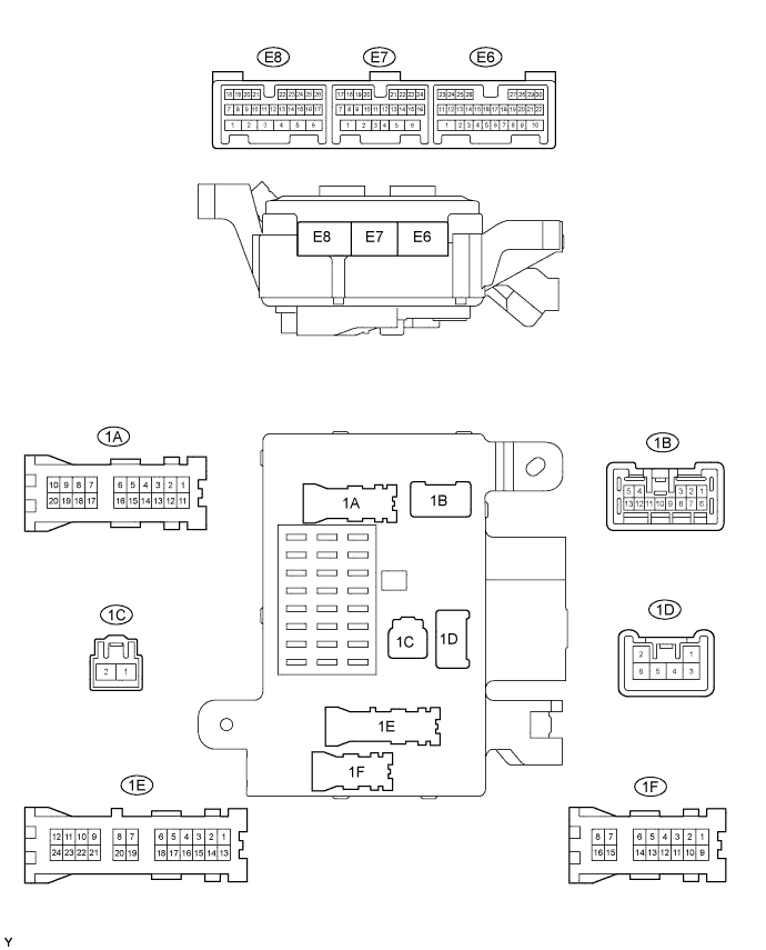
Disconnect the E7, E8 and 1A main body ECU connectors.
Measure the voltage of the wire harness side connectors.
Terminal No. (Symbol)
Wiring Color
Terminal Description
Condition
Specified Condition
E7-7 (BCTY) - Body ground
W - Body ground
Back door courtesy switch and back window courtesy switch input
Back door CLOSED → OPEN
11 to 14 V → Below 1 V
E7-11 (RLCY) - Body ground
P-B - Body ground
Rear door courtesy switch signal (LH)
Rear door (Driver side) CLOSED → OPEN
11 to 14 V → Below 1 V
E7-12 (RRCY) - Body ground
P-L - Body ground
Rear door courtesy switch signal (RH)
Rear door (Front passenger side) CLOSED → OPEN
11 to 14 V → Below 1 V
E7-23 (DCTY) - Body ground
R-B - Body ground
Front door courtesy switch signal (Driver side)
Driver door CLOSED → OPEN
11 to 14 V → Below 1 V
E7-24 (PCTY) - Body ground
R-B - Body ground
Front door courtesy switch signal (Passenger side)
Front passenger door CLOSED → OPEN
11 to 14 V → Below 1 V
E8-14 (KSW) - Body ground
G-Y - Body ground
Key unlock switch condition signal
Key inserted → Removed
Below 1 V → 11 to 14 V
1A-7 (GND2) - Body ground)
W - Body ground
Ground
Always
Below 1 V
- HINT:
- If the result is not as specified, there may be a malfunction in the wire harness.
| CHECK MAIN BODY ECU (for RHD) |
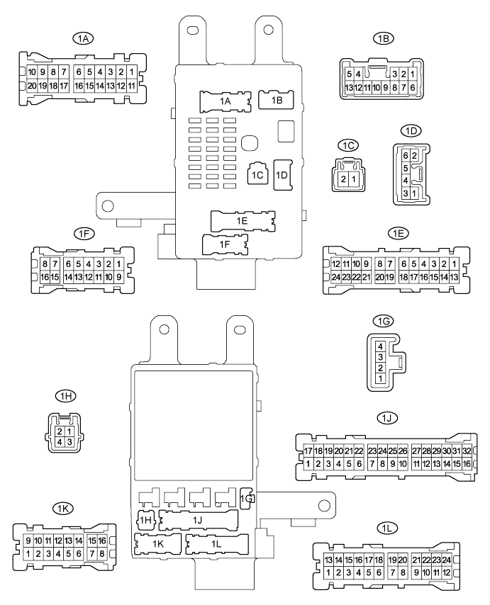
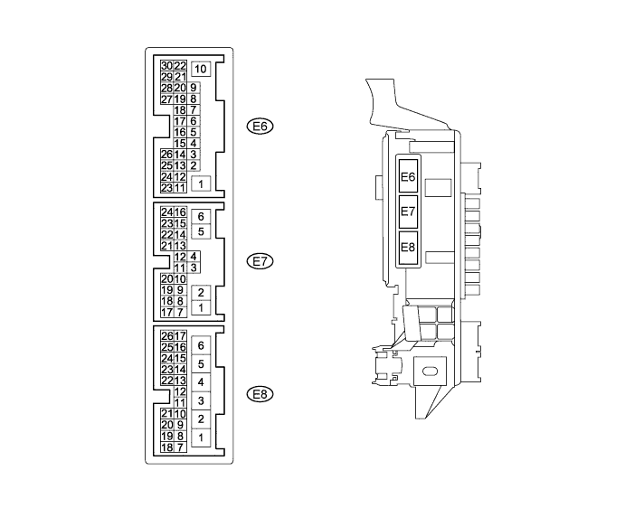
Disconnect the E7, E8 and 1H main body ECU connectors.
Measure the voltage of the wire harness side connectors.
Terminal No. (Symbol)
Wiring Color
Terminal Description
Condition
Specified Condition
E7-7 (BCTY) - Body ground
W - Body ground
Back door courtesy switch and back window courtesy switch input
Back door CLOSED → OPEN
11 to 14 V → Below 1 V
E7-11 (RLCY) - Body ground
P-B - Body ground
Rear door courtesy switch signal (LH)
Rear door (Driver side) CLOSED → OPEN
11 to 14 V → Below 1 V
E7-12 (RRCY) - Body ground
P-L - Body ground
Rear door courtesy switch signal (RH)
Rear door (Front passenger side) CLOSED → OPEN
11 to 14 V → Below 1 V
E7-23 (DCTY) - Body ground
R-B - Body ground
Front door courtesy switch signal (Driver side)
Driver door CLOSED → OPEN
11 to 14 V → Below 1 V
E7-24 (PCTY) - Body ground
G - Body ground
Front door courtesy switch signal (Passenger side)
Front passenger door CLOSED → OPEN
11 to 14 V → Below 1 V
E8-14 (KSW) - Body ground
G-Y - Body ground
Key unlock switch condition signal
Key inserted → Removed
Below 1 V → 11 to 14 V
1H-2 (GND2) - Body ground)
W-B - Body ground
Ground
Always
Below 1 V
- HINT:
- If the result is not as specified, there may be a malfunction in the wire harness.
| COMBINATION METER INTERNAL CIRCUIT |
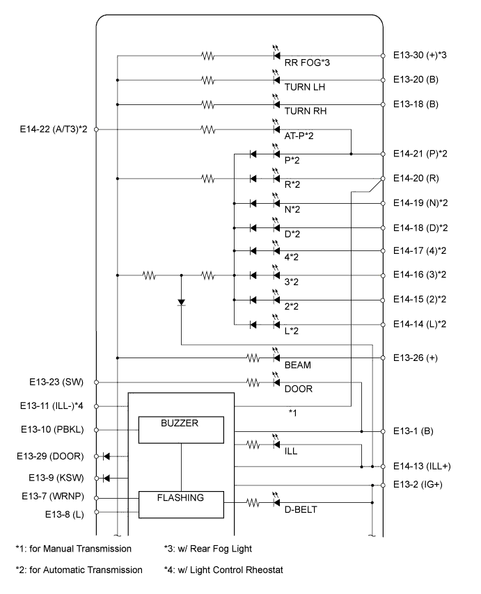
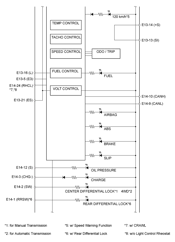
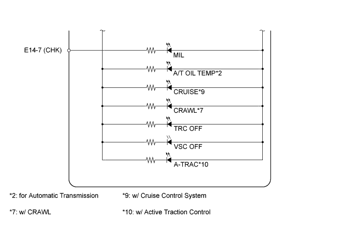
| Terminal No. |
Wire Harness Side |
|
| E13 |
1 |
Battery |
| 2 |
Ignition switch |
|
| 5 |
Fuel sender gauge assembly |
|
| 7 |
Air conditioning amplifier |
|
| 8 |
Front seat inner belt assembly (Driver side) |
|
| 9 |
Main body ECU |
|
| 10 |
Front seat inner belt assembly (Passenger side) |
|
| 11 |
Light control rheostat*2 |
|
| 13 |
Skid control ECU |
|
| 14 |
4P-OUT (Other parts) |
|
| 16 |
Fuel sender gauge assembly |
|
| 18 |
Turn signal flasher assembly |
|
| 20 |
Turn signal flasher assembly |
|
| 21 |
Body ground |
|
| 23 |
Main body ECU |
|
| 26 |
Headlight Dimmer Switch |
|
| 29 |
Main body ECU |
|
| 30 |
Rear fog light switch*4 |
|
| E14 |
1 |
Differential lock switch*5 |
| 2 |
Transfer indicator switch*1 |
|
| 4WD control ECU*3 | ||
| 3 |
Generator |
|
| 7 |
ECM |
|
| 9 |
CAN communication line (CANL) |
|
| 10 |
CAN communication line (CANH) |
|
| 12 |
Engine oil pressure switch |
|
| 13 |
TAIL relay |
|
| 14 |
Shift lock control ECU*3 |
|
| 15 |
Shift lock control ECU*3 |
|
| 16 |
Park/Neutral position switch*3 |
|
| 17 |
Shift lock control ECU*3 |
|
| 18 |
Shift lock control ECU*3 |
|
| 19 |
Park/Neutral position switch*3 |
|
| 20 |
Back-up light switch*1 |
|
| Park/Neutral position switch*3 | ||
| 21 |
Park/Neutral position switch*3 |
|
| 22 |
Transfer indicator switch (Neutral position)*3 |
|
| 24 |
Each illumination part*6,*7 |
|
- *1: for Manual Transmission
- *2: w/ Light Control Rheostat
- *3: for Automatic Transmission
- *4: w/ Rear Fog Light
- *5: w/ Rear Differential Lock
- *6: w/ CRAWL
- *7: w/o Light Control Rheostat