Some of these service operations affect the SRS airbag system. Read the precautionary notices concerning the SRS airbag system before servicing (Click here).
HINT:
The procedure described below is for the RH side. Use the same procedure for both the RH and LH sides, unless otherwise specified.
1.
INSTALL FRONT SHOULDER BELT ANCHOR ADJUSTER ASSEMBLY
Insert the hook into the body hole and provisionally install the shoulder belt anchor adjuster with the 2 bolts.
Tighten the upper bolt and then the lower bolt.
Torque:
42 N*m{
428 kgf*cm
, 31 ft.*lbf
}
2.
INSTALL FRONT SEAT OUTER BELT ASSEMBLY
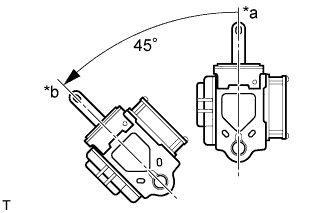
Check the angle of inclination required to lock the retractor.
Text in Illustration
*a
Unlock
*b
Lock
Gently incline the retractor from its initial position. Check that the belt does not lock when the retractor is inclined 15° or less in any direction. Also, check that the belt locks when the inclination of the retractor is 45° or more.
NOTICE:
Do not disassemble the retractor.
If the operation is not as specified, replace the front seat outer belt.
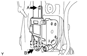
Hook the lower stay of the retractor onto the 2 body hooks and provisionally install the retractor with the 2 bolts.
Tighten bolt A and then bolt B.
Torque:
8.5 N*m{
87 kgf*cm
, 75 in.*lbf
}
for bolt A
42 N*m{
428 kgf*cm
, 31 ft.*lbf
}
for bolt B
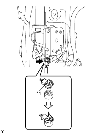
Connect the pretensioner connector.
Text in Illustration
*1
Locking Button
Lock the locking button of the pretensioner connector.
NOTICE:
Securely lock the locking button.
Install the through anchor with the nut.
Torque:
42 N*m{
428 kgf*cm
, 31 ft.*lbf
}
Make sure that the shoulder anchor rotates smoothly.
Check that the ELR locks.
NOTICE:
Perform the check with the front seat outer belt installed.
With the belt installed, check that the belt locks when it is pulled out quickly. If the operation is not as specified, replace the front seat outer belt.
3.
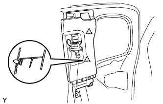
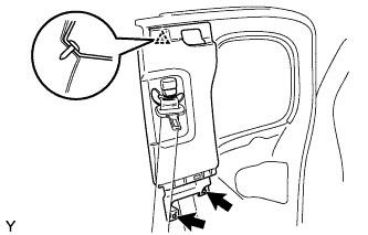
INSTALL CENTER PILLAR UPPER GARNISH
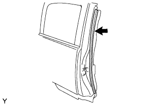
Engage the 2 clips and install the center pillar upper garnish.
Install the 2 screws.
Install the clip.
4.
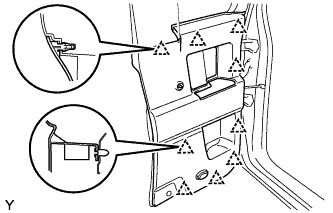
INSTALL ACCESS DOOR TRIM BOARD SUB-ASSEMBLY
Engage the 9 clips and install the rear door trim board.
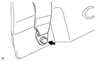
Install the front seat belt outer (floor side) with the bolt.
Torque:
42 N*m{
428 kgf*cm
, 31 ft.*lbf
}
5.
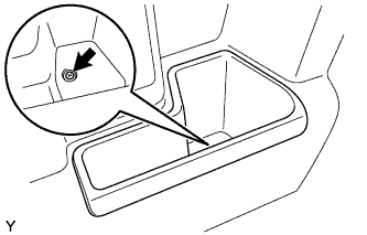
INSTALL CUP HOLDER
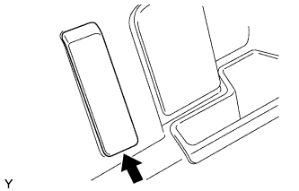
Install the No. 1 cup holder with the screw.
6.
INSTALL ACCESS DOOR INSIDE HANDLE SUB-ASSEMBLY
Install the rear door inside handle with the snap ring onto the access panel inside handle.
7.
INSTALL LAP BELT OUTER ANCHOR COVER
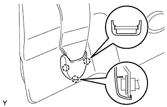
Engage the 3 claws and install the lap belt outer anchor cover.