Home › BODY › EXTERIOR › REAR BUMPER (w/ Rear Fog Light)DISASSEMBLY
Removal / installation · Vehicles built Nov 2010 – Jul 2012
Versions by build date: Jul 2007 – Oct 2010 Nov 2010 – Jul 2012 from Aug 2012
1.
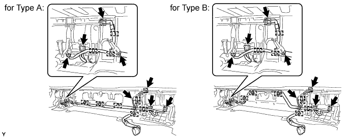
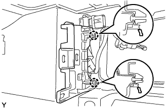
REMOVE NO. 8 FLOOR WIRE
Disconnect the connectors.
Disengage the clamps and remove the floor wire.
2.
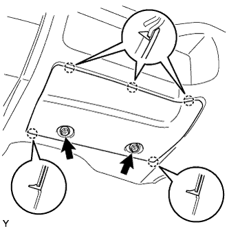
REMOVE REAR BUMPER PLATE LH
Remove the 2 screws.
Disengage the 5 claws and remove the rear bumper plate.
3.
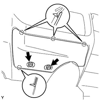
REMOVE REAR BUMPER PLATE RH
Remove the 2 screws.
Disengage the 4 claws and remove the rear bumper plate.
4.
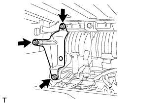
REMOVE REAR BUMPER SIDE RETAINER RH
Remove the 3 screws and rear bumper extension retainer.
5.
REMOVE REAR BUMPER SIDE RETAINER LH
HINT:
Use the same procedure as for the RH side.
6.
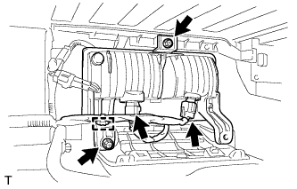
REMOVE REAR FOG LIGHT ASSEMBLY LH
Disconnect the 2 connectors and wire harness clamp.
Remove the 2 screws and rear fog light.
7.
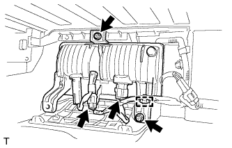
REMOVE REAR FOG LIGHT ASSEMBLY RH
Disconnect the 2 connectors and wire harness clamp.
Remove the 2 screws and rear fog light.
8.
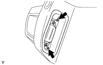
REMOVE LICENSE PLATE BRACKET HANGER ASSEMBLY (for LH Side)
Remove the 2 screws.
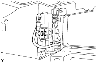
Disengage the wire harness clamp and separate the wire harness.
Disengage the 2 claws and remove the license plate bracket hanger assembly.
NOTICE:
Be careful when disengaging the claws because they are easily broken.
9.
REMOVE LICENSE PLATE BRACKET HANGER ASSEMBLY (for RH Side)
HINT:
Use the same procedure as for the LH side.
10.
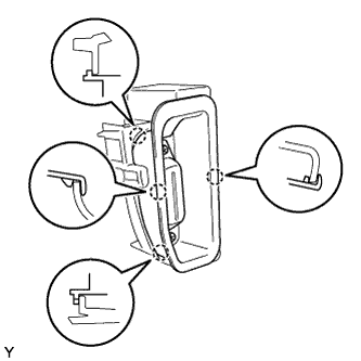
REMOVE REAR BUMPER EXTENSION MOULDING LH
Disengage the 4 claws and remove the rear bumper extension moulding.
11.
REMOVE REAR BUMPER EXTENSION MOULDING RH
HINT:
Use the same procedure as for the LH side.
12.
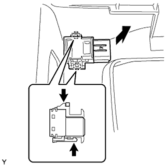
REMOVE ULTRASONIC SENSOR
Disconnect the sensor connector.
While pushing down on the lever with a finger to release the claw, disengage the claw on the other side to remove the ultrasonic sensor.
HINT:
The types of the claws on the top and bottom of the sensor are different. Observe the claws carefully before attempting to remove the sensor.
13.
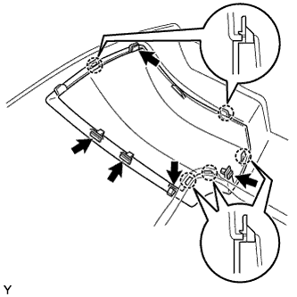
REMOVE REAR BUMPER PAD LH
Remove the 5 retainers. Disengage the 5 claws and remove the rear bumper pad.
14.
REMOVE REAR BUMPER PAD RH
HINT:
Use the same procedure as for the LH side.
15.
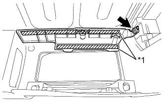
REMOVE REAR BUMPER UPPER COVER LH
Remove the screw.
Text in Illustration
*1
Double-sided Tape
Using an infrared light, heat the rear bumper upper cover.
Heating Temperature:
Item
Temperature
Rear Bumper Cover
40 to 60°C (104 to 140°F)
CAUTION:
Do not burn yourself on the hot rear bumper cover or with the infrared light.
NOTICE:
Do not heat the rear bumper cover excessively.
Remove any tape remaining on the rear bumper cover.
Pull the rear bumper upper cover toward you, and while peeling off the double-sided tape, remove the rear bumper upper cover.
16.
REMOVE REAR BUMPER UPPER COVER RH
HINT:
Use the same procedure as for the LH side.
17.
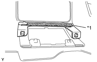
REMOVE REAR BUMPER EXTENSION MOUNTING BRACKET LH
Using an infrared light, heat the rear bumper extension mounting bracket.
Heating Temperature:
Item
Temperature
Rear Bumper Cover
40 to 60°C (104 to 140°F)
CAUTION:
Do not burn yourself on the hot rear bumper cover or with the infrared light.
NOTICE:
Do not heat the rear bumper cover excessively.
Remove any tape remaining on the rear bumper cover.
Pull the rear bumper extension mounting bracket toward you, and while peeling off the double-sided tape, remove the rear bumper extension mounting bracket.
Text in Illustration
*1
Double-sided Tape
18.
REMOVE REAR BUMPER EXTENSION MOUNTING BRACKET RH
HINT:
Use the same procedure as for the LH side.