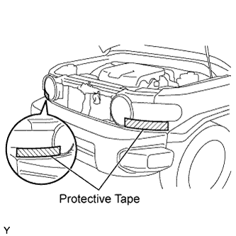
The procedure described below is for the LH side. Use the same procedure for both the RH and LH sides, unless otherwise specified.
1.
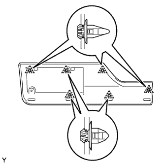
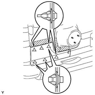
INSTALL BACK DOOR OUTSIDE MOULDING RH
Install 6 new clips in the positions shown in the illustration.
NOTICE:
If you install the clips wrongly, the installation of the back door outside moulding will be improper.
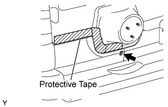
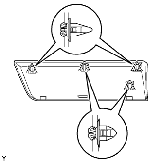
Engage the 6 clips and install the back door outside moulding.
Tighten the screw.
Remove the protective tape.
2.
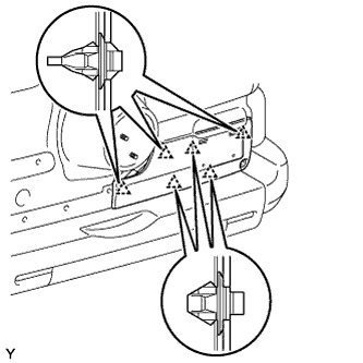
INSTALL BACK DOOR OUTSIDE MOULDING LH
Install 6 new clips in the positions shown in the illustration.
NOTICE:
If you install the clips wrongly, the installation of the back door outside moulding will be improper.
Engage the 6 clips and install the back door outside moulding.
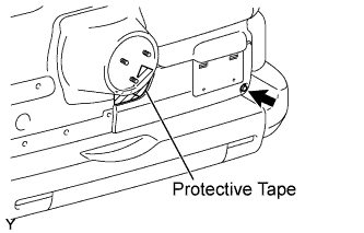
Tighten the screw.
Remove the protective tape.
3.
INSTALL SPARE TIRE
Torque:
88 N*m{
897 kgf*cm
, 65 ft.*lbf
}
4.
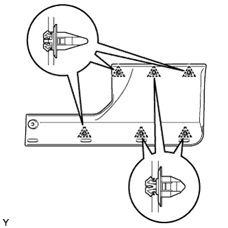
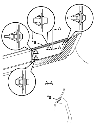
INSTALL REAR DOOR OUTSIDE MOULDING SUB-ASSEMBLY
Install 4 new clips in the positions shown in the illustration.
NOTICE:
If you install the clips wrongly, the installation of the rear door outside moulding sub-assembly will be improper.
Clean the attachment surface.
Using an infrared light, heat the double-sided tape remaining on the vehicle body.
Heating Temperature
Item
Temperature
Vehicle Body
40 to 60°C (104 to 140°F)
CAUTION:
Do not burn yourself with the vehicle body or infrared light.
NOTICE:
Do not heat the vehicle body excessively.
Using a piece of cloth, rub the remaining double-sided tape off the vehicle body while it is hot from the infrared light.
NOTICE:
Installing the rear door outside moulding sub-assembly while any double-sided tape remains on the vehicle body may cause adhesion failure. Therefore, completely remove the double-sided adhesive tape.
Using a non-residue solvent, clean the attachment surface.
Remove the release paper from the face of the rear door outside moulding sub-assembly.
Text in Illustration
*a
Double-sided Tape
HINT:
After removing the release paper, keep the exposed adhesive free from foreign matter.
Engage the 4 clips and install the new rear door outside moulding sub-assembly.
Install the nut.
Torque:
5.0 N*m{
51 kgf*cm
, 44 in.*lbf
}
Remove the protective tape.
5.
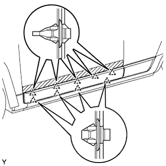
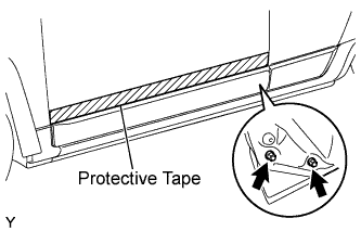
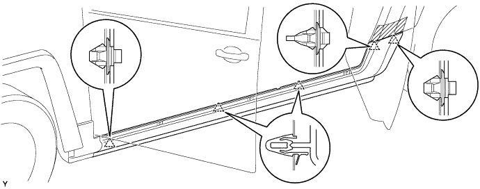
INSTALL FRONT DOOR OUTSIDE MOULDING SUB-ASSEMBLY
Install 9 new clips in the positions shown in the illustration.
NOTICE:
If you install the clips wrongly, the installation of the rear door outside moulding will be improper.
Engage the 9 clips and install the front door outside moulding.
Tighten the 2 nuts.
Torque:
5.0 N*m{
50 kgf*cm
, 44 in.*lbf
}
Remove the protective tape.
6.
INSTALL QUARTER PANEL MOULDING PAD
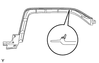
HINT:
Only follow this procedure when replacing the quarter outside moulding pad.
Install a new quarter outside moulding pad in the position shown in the illustration.
7.
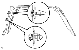
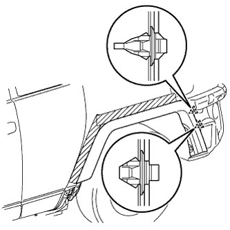
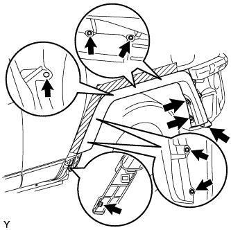
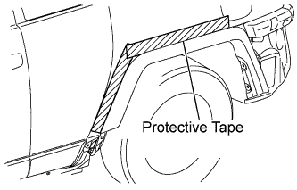
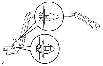
INSTALL QUARTER OUTSIDE MOULDING SUB-ASSEMBLY
Install 2 new clips in the positions shown in the illustration.
NOTICE:
If you install the clips wrongly, the installation of the quarter outside moulding will be improper.
Engage the 2 clips and install the quarter outside moulding.
Tighten the 8 screws
Torque:
5.0 N*m{
50 kgf*cm
, 44 in.*lbf
}
Install the clip.
Remove the protective tape.
8.
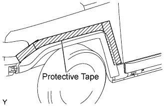
INSTALL FRONT FENDER OUTSIDE MOULDING PAD
HINT:
Only follow this procedure when replacing the front wheel opening extension pad.
Install a new front wheel opening extension pad in the position shown in the illustration.
9.
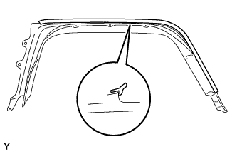
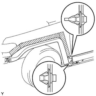
INSTALL FRONT FENDER MOULDING SUB-ASSEMBLY
Install 2 new clips in the positions shown in the illustration.
NOTICE:
If you install the clips wrongly, the installation of the front fender moulding will be improper.
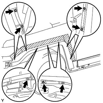
Engage the 2 clips and install the front fender moulding.
Tighten the 5 screws.
Torque:
5.0 N*m{
50 kgf*cm
, 44 in.*lbf
}
Install the 2 clips
Remove the protective tape.
10.
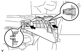
INSTALL FRONT BUMPER SIDE SUPPORT
Engage the 2 claws and install the front bumper side support.
Tighten the 2 screws.
Torque:
3.0 N*m{
30 kgf*cm
, 27 in.*lbf
}
11.
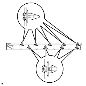
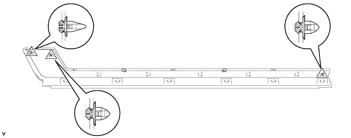
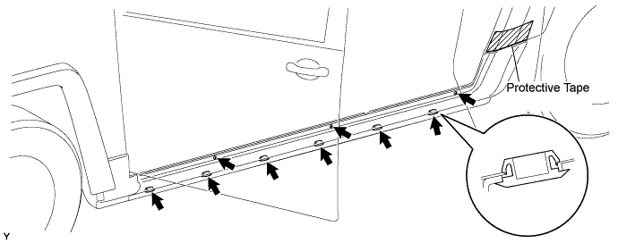
INSTALL ROCKER PANEL MOULDING
Install 3 clips in the positions shown in the illustration.
NOTICE:
If you install the clips wrongly, the installation of the rocker panel moulding will be improper.
Engage the 5 clips and install the rocker panel moulding.
Tighten the 3 screws.
Torque:
5.0 N*m{
50 kgf*cm
, 44 in.*lbf
}
Install the 6 retainers.
12.
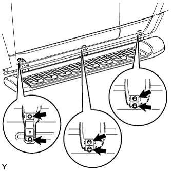
INSTALL SIDE STEP SUB-ASSEMBLY
Install the step with 6 bolts.
Torque:
20 N*m{
200 kgf*cm
, 14 ft.*lbf
}
13.
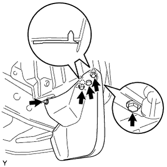
INSTALL QUARTER PANEL MUDGUARD
Align the 2 pins of the quarter panel mudguard with the installation hole of the quarter outside moulding.
Install the quarter panel mudguard with the 4 screws.
Torque:
5.0 N*m{
50 kgf*cm
, 44 in.*lbf
}
Install the clip.
14.
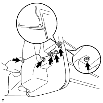
INSTALL FRONT FENDER MUDGUARD
Align the pin of the front fender mudguard with the installation hole of the front fender moulding.
Install the front fender mudguard with the 5 screws.
Torque:
5.0 N*m{
50 kgf*cm
, 44 in.*lbf
}
Install the clip.
15.
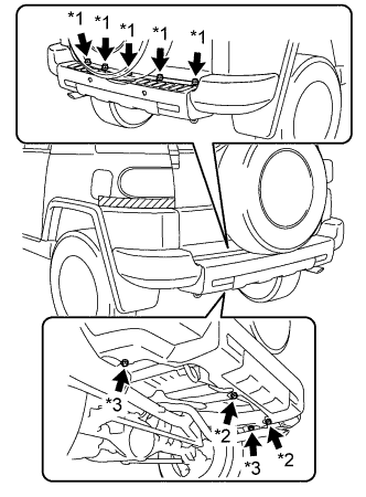
INSTALL REAR BUMPER COVER
Engage the 6 claws and the 2 clips and install the rear bumper cover.
Connect the connector.
HINT:
If the vehicle is equipped with back sonar, connect the connector and install the floor wire.
Connect the clamp and install the floor wire.
Install the 7 bolts and the 2 screws.
Text in Illustration
*1
Bolt A
*2
Bolt B
*3
Screw
Torque:
for bolt A:
8.0 N*m{
82 kgf*cm
, 71 in.*lbf
}
for bolt B:
10 N*m{
102 kgf*cm
, 7 ft.*lbf
}
for screw:
3.0 N*m{
31 kgf*cm
, 27 in.*lbf
}
Remove the protective tape.
16.
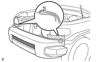
INSTALL FRONT BUMPER COVER
Engage the 2 claws and install the front bumper cover.
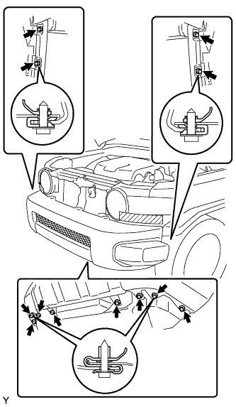
Tighten the 8 screws and the 4 bolts.
Torque:
3.0 N*m{
30 kgf*cm
, 27 in.*lbf
}
for screw
8.0 N*m{
80 kgf*cm
, 71 in.*lbf
}
for bolt
Install the 5 clips.
Remove the protective tape.
17.
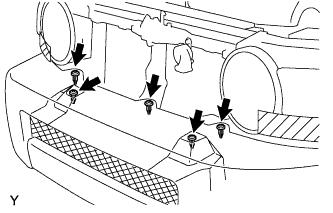
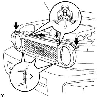
INSTALL RADIATOR GRILLE
Engage the 5 clips and install the radiator grille.
Tighten the 2 screws.
Torque:
3.0 N*m{
30 kgf*cm
, 27 in.*lbf
}
Install the 2 clips.
18.
CONNECT CABLE TO NEGATIVE BATTERY TERMINAL (w/ Back Sonar)