DISASSEMBLY
Removal / installation · Vehicles built Jul 2007 – Jul 2008
Versions by build date: Jul 2007 – Jul 2008 from Aug 2008
| 1.
DISCONNECT CABLE FROM NEGATIVE BATTERY TERMINAL |
|
| 2.
REMOVE SPARE DISC WHEEL |
|
| 3.
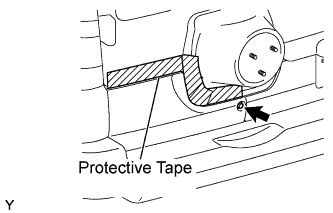
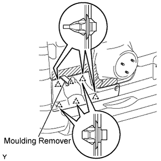
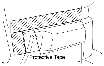
REMOVE BACK DOOR OUTSIDE MOULDING LH
|
 |
- Apply protective tape to the back door panel in the area around the back door outside moulding.
Remove the screw.
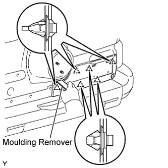
- Using a moulding remover, disengage the 6 clips and remove the back door outside moulding.
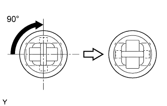
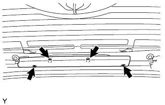
- Turn the clips 90° clockwise and remove them.
| 4.
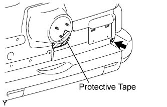
REMOVE BACK DOOR OUTSIDE MOULDING RH
|
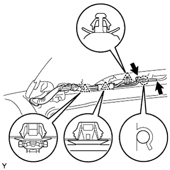
|
- Apply protective tape to the back door panel in the area around the back door outside moulding.
Remove the screw.
- Using a moulding remover, disengage the 6 clips and remove the back door outside moulding.
- Turn the clips 90° clockwise and remove them.
| 5.
REMOVE SPARE WHEEL CARRIER BRACKET SUB-ASSEMBLY |
|
Remove the 2 bolts, 2 nuts and the spare wheel carrier bracket.
| 6.
REMOVE BACK DOOR TRIM COVER RH |
|
Using a screwdriver with its tip wrapped in protective tape, disengage the 3 claws and remove the back door trim cover.
| 7.
REMOVE BACK DOOR TRIM COVER LH |
|
- HINT:
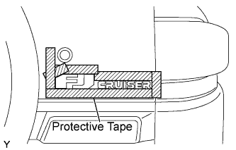
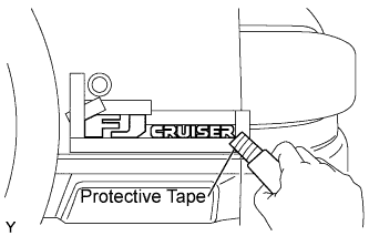
- Use the same procedure as described for the RH side.
| 8.
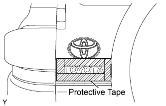
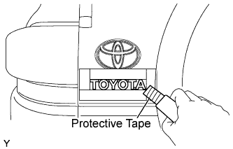
REMOVE DOOR TRIM RETAINER CAP |
|
Using a screwdriver with its tip wrapped in protective tape, disengage the 2 claws and remove the door trim retainer cap.
| 9.
REMOVE BACK DOOR TRIM BOARD |
|
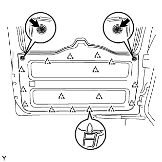
Remove the 2 screws.
Disengage the 16 clips and remove the back door trim board.
| 10.
REMOVE BACK DOOR SERVICE HOLE COVER |
|
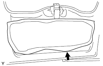
Remove the back door service hole cover.
- NOTICE:
- Remove any tape remaining on the door side.
| 11.
REMOVE REAR WIPER ARM AND BLADE ASSEMBLY (w/ Rear Wiper)
|
|
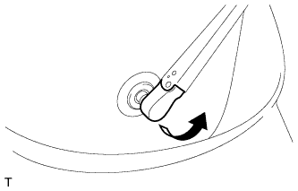
- Open the rear wiper arm head cap.
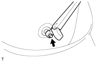
- Remove the nut and the rear wiper arm and blade.
| 12.
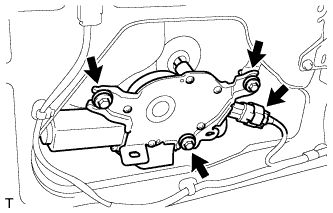
REMOVE REAR WIPER MOTOR (w/ Rear Wiper)
|
|
- Disconnect the connector.
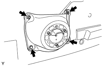
Remove 3 bolts and the rear wiper motor.
| 13.
REMOVE REAR WIPER MOTOR GROMMET (w/ Rear Wiper) |
|
| 14.
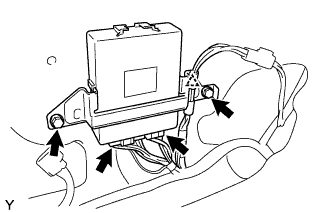
REMOVE MULTIPLEX NETWORK DOOR ECU |
|
Disconnect the 2 connectors and harness clamp.
Remove the 2 screws and the multiplex network door ECU.
| 15.
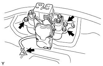
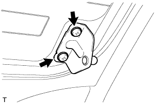
REMOVE BACK WINDOW LOCK ASSEMBLY
|
|
- Disconnect the connector and clamp.
Remove the 3 bolts and the back window lock.
| 16.
REMOVE BACK DOOR OUTSIDE GARNISH SUB-ASSEMBLY
|
|
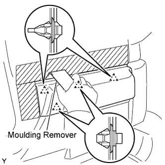
- Apply protective tape to the back door panel in the area around the back door outside garnish.
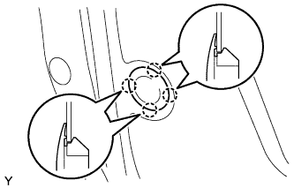
- Using a clip remover, disengage the 4 claws and remove the plug hole.
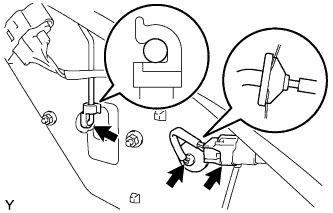
- Disconnect the license light connector.
Disconnect the back door lock rod.
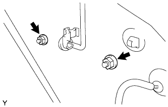
- Remove the 2 nuts.
- Using a moulding remover, disengage the 4 clips and remove the back door outside garnish.
| 17.
REMOVE BACK DOOR LOCK ASSEMBLY
|
|
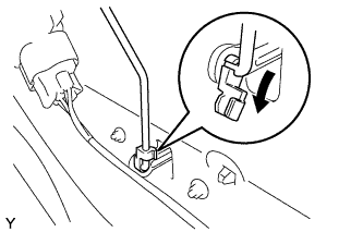
- Disconnect the back door lock rod as shown in the illustration.
Disconnect the connector.
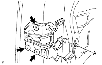
- Loosen bolt A.
Using "Torx" socket wrench T30, remove the 3 screws and the back door lock.
- NOTICE:
- Do not drop or damage the back door lock when removing the screws.
- HINT:
- Remove the back door lock through the service hole.
| 18.
REMOVE BACK DOOR LOCK CYLINDER ASSEMBLY |
|
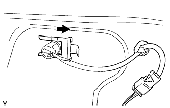
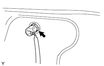
Disconnect the connector and the 2 clamps.
- Remove the retainer and the back door lock cylinder.
| 19.
REMOVE NO. 1 REAR SPOILER COVER |
|
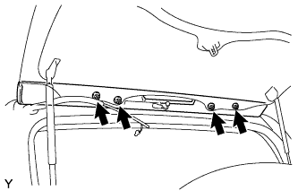
Remove the 4 screws and No. 1 rear spoiler cover.
| 20.
REMOVE REAR SPOILER
|
|
- Disconnect high mounted stop light connector.
Using a clip remover, remove the 3 clamps.
Remove the washer hose from the claw of the rear spoiler.
Disconnect the washer hose.
- Remove the 4 nuts.
| 21.
REMOVE HIGH MOUNTED STOP LIGHT ASSEMBLY
|
|
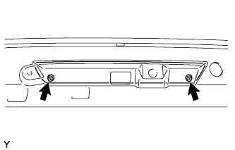
- Remove the 2 screws and the high mounted stop light.
| 22.
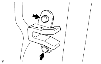
REMOVE BACK DOOR SIDE FEMALE STOPPER SUB-ASSEMBLY |
|
Remove the 2 bolts and back door side female stopper.
| 23.
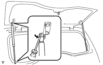
REMOVE BACK WINDOW SUPPORT LH
|
|
Using a screwdriver with its tip wrapped in protective tape, remove the 2 stop rings and back window support.
- NOTICE:
- Do not touch the rod of the back window support with gloves, to avoid fibers from adhering.
- When foreign matter adheres to the rod, it prevents the rod from moving smoothly and reduces its holding power.
- HINT:
- Support the back door glass by hand while removing the back window support.
| 24.
REMOVE BACK WINDOW SUPPORT RH |
|
- HINT:
- Use the same procedure as described for the LH side.
| 25.
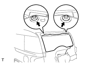
REMOVE BACK DOOR GLASS
|
|
Disconnect the 2 defogger connectors.
- Remove the 2 nuts and the back door glass.
| 26.
REMOVE BACK WINDOW STAY UPPER BRACKET RH
|
|
Remove the 2 screws, the retainer and the back window stay upper bracket.
| 27.
REMOVE BACK WINDOW STAY UPPER BRACKET LH |
|
- HINT:
- Use the same procedure as described for the RH side.
| 28.
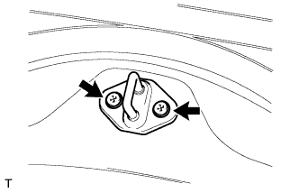
REMOVE BACK WINDOW LOCK STRIKER ASSEMBLY
|
|
Remove the 2 screws, the retainer and the back window lock striker.
| 29.
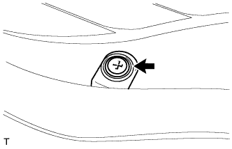
REMOVE BACK DOOR OUTSIDE HANDLE
|
|
Remove the screw and the back door outside handle.
Remove the bush.
| 30.
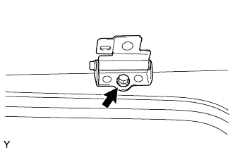
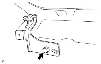
REMOVE BACK DOOR HINGE ASSEMBLY RH |
|
Remove the bolt and the back door hinge.
| 31.
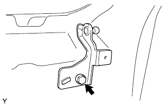
REMOVE BACK DOOR HINGE ASSEMBLY LH |
|
- HINT:
- Use the same procedure as described for the RH side.
| 32.
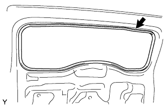
REMOVE NO. 2 BACK DOOR WEATHERSTRIP |
|
Remove the No. 2 back door weatherstrip.
- NOTICE:
- Remove any tape remaining on the door side.
| 33.
REMOVE BACK DOOR STAY UPPER BRACKET RH |
|
Remove the bolt and the back door stay upper bracket.
| 34.
REMOVE BACK DOOR STAY UPPER BRACKET LH |
|
Remove the bolt and the back door stay upper bracket.
| 35.
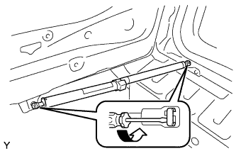
REMOVE BACK DOOR SUPPORT
|
|
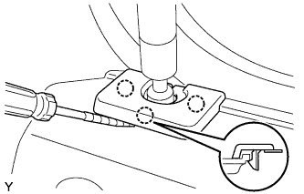
Using a screwdriver with its tip wrapped in protective tape, remove the 2 stop rings and back door support.
- NOTICE:
- Do not touch the rod of the back door support with gloves, to avoid fibers from adhering.
- When foreign matter adheres to the rod, it prevents the rod from moving smoothly and reduces its holding power.
| 36.
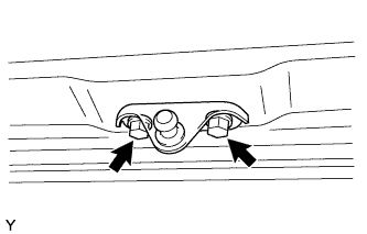
REMOVE BACK DOOR DAMPER STAY LOWER BRACKET |
|
Remove the 2 bolts and the back door damper stay lower bracket.
| 37.
REMOVE NO. 1 BACK DOOR NAME PLATE
|
|
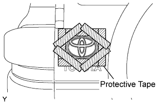
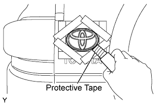
- Apply protective tape to the back door panel in the area around the No. 1 back door name plate.
Using an infrared light, heat the No. 1 back door name plate.
- CAUTION:
- Do not burn yourself with the heated back door panel or infrared light.
- HINT:
- Heat at 40 to 60°C (104 to 140°F) for 1 to 2 minutes.
- Using a gasket scraper with its tip wrapped in protective tape, gradually peel the adhesive surface and remove the No. 1 back door name plate.
Remove the protective tape.
| 38.
REMOVE NO. 2 BACK DOOR NAME PLATE
|
|
- Apply protective tape to the back door panel in the area around the No. 2 back door name plate.
Using an infrared light, heat the No. 2 back door name plate.
- CAUTION:
- Do not burn yourself with the heated back door panel or infrared light.
- HINT:
- Heat at 40 to 60°C (104 to 140°F) for 1 to 2 minutes.
- Using a gasket scraper with its tip wrapped in protective tape, gradually peel the adhesive surface and remove the No. 2 back door name plate.
Remove the protective tape.
| 39.
REMOVE REAR NAME PLATE
|
|
- Apply protective tape to the back door panel in the area around the rear name plate.
Using an infrared light, heat the rear name plate.
- CAUTION:
- Do not burn yourself with the heated back door panel or infrared light.
- HINT:
- Heat at 40 to 60°C (104 to 140°F) for 1 to 2 minutes.
- Using a gasket scraper with its tip wrapped in protective tape, gradually peel the adhesive surface and remove the rear name plate.
Remove the protective tape.
| 40.
REMOVE CUSHION |
|
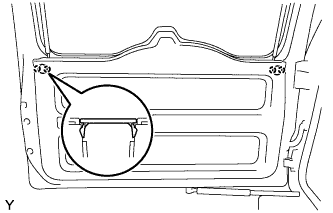
Remove the 2 cushions.
| 41.
REMOVE HOLE PLUG |
|
Remove the 2 hole plugs.