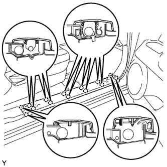
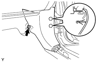
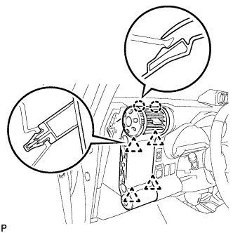
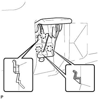
Disengage the 4 clips and 2 claws and remove the instrument panel register.
NOTICE:
To avoid breakage of the register, remove the instrument panel register with the shut damper of the register open.
Pull the instrument panel register up diagonally to remove it.
5.
SEPARATE HOOD LOCK CONTROL LEVER SUB-ASSEMBLY
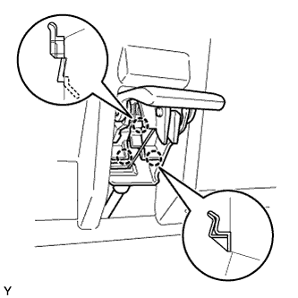
Disengage the 3 claws and separate the hood lock control lever.
6.
SEPARATE FUEL LID LOCK OPEN LEVER SUB-ASSEMBLY
Disengage the 3 claws and separate the fuel lid lock open lever.
7.
REMOVE INSTRUMENT PANEL FINISH PLATE
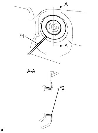
Using a screwdriver with its tip wrapped in protective tape, remove the instrument panel finish plate.
Text in Illustration
*1
Protective Tape
*2
Instrument Panel Finish Plate
8.
REMOVE LOWER INSTRUMENT PANEL FINISH PANEL
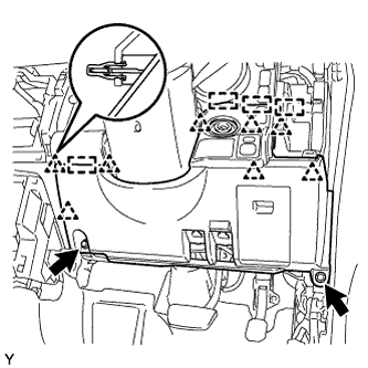
Remove the 2 <E> bolts.
Disengage the 8 clips and 4 guides.
Disconnect the connectors and remove the lower instrument panel finish panel.
9.
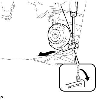
REMOVE TRANSPONDER KEY AMPLIFIER
Disconnect the connector.
Text in Illustration
*1
Protective Tape
Using a screwdriver with its tip wrapped in protective tape, disengage the 2 claws and remove the transponder key amplifier.
10.
REMOVE UNLOCK WARNING SWITCH ASSEMBLY
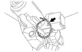
Cut the cable tie.
Disconnect the connector.
Separate the un-lock warning switch connector from the ignition or starter switch.
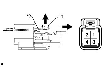
Disengage the secondary locking device.
Text in Illustration
*1
Secondary Locking Device
*2
Locking Lug
Using a screwdriver, disengage the locking lug of terminals 3 and 4, and pull the terminals out from the rear side of the un-lock warning switch connector.
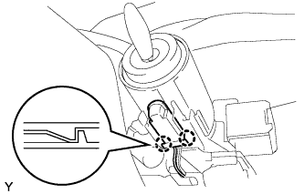
Disengage the 2 claws and remove the un-lock warning switch.