INSTALLATION
Removal / installation · Vehicles built Jul 2007 – Oct 2010
Versions by build date: Jul 2007 – Oct 2010 from Nov 2010
| 1.
INSTALL PARKING BRAKE CABLE CLAMP |
 |
Install the parking brake cable clamp onto the parking brake cable.
| 2.
INSTALL PARKING BRAKE CABLE |
|
Install the parking brake cable with the 5 bolts.
-
Torque:
- 13 N*m{
127 kgf*cm
, 9 ft.*lbf
}
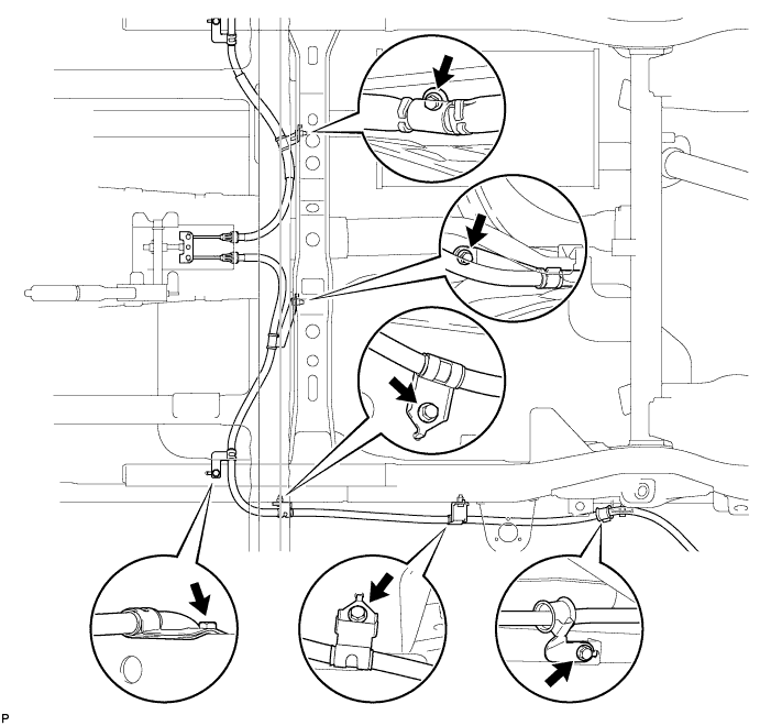

- Install the parking brake cable to the parking brake plate with the 2 bolts.
-
Torque:
- 8.0 N*m{
82 kgf*cm
, 71 in.*lbf
}
- Install the spring cap into the body.
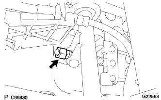
Connect the cable end to the parking brake pull rod.
| 3.
INSTALL PARKING BRAKE CABLE HEAT INSULATOR (for RH Side) |
|
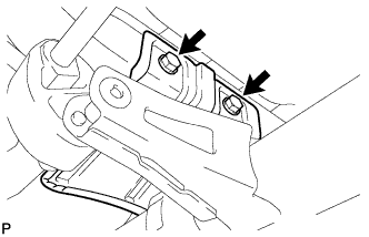
Install the heat insulator with the 2 bolts.
-
Torque:
- 13 N*m{
127 kgf*cm
, 9 ft.*lbf
}
| 4.
APPLY HIGH TEMPERATURE GREASE
|
|
Apply high temperature grease to the surface of the backing plate which is in contact with the shoe.
| 5.
INSTALL PARKING BRAKE SHOE
|
|
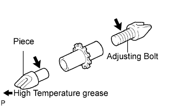
Apply high temperature grease to the adjusting bolt and piece.
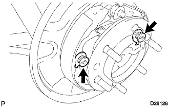
Using needle-nose pliers, connect the parking brake cable to the parking brake shoe lever.
- Install the No. 1 shoe, hold down spring pin, hold down compression spring and 2 hold down spring cups.
Install the return tension spring and shoe adjusting screw set.
Install the No. 2 shoe, hold down spring pin, hold down compression spring and 2 hold down spring cups.
| 6.
INSTALL PARKING BRAKE SHOE STRUT
|
|
Attach the compression spring and parking brake shoe strut to the No. 2 and No. 1 shoes.
| 7.
INSTALL PARKING BRAKE SHOE RETURN TENSION SPRING
|
|
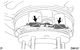
Using needle-nose pliers, install the 2 return tension springs.
- HINT:
- First install the front side spring then install the rear side spring.
| 8.
CHECK PARKING BRAKE INSTALLATION
|
|
Check that each part is installed properly.
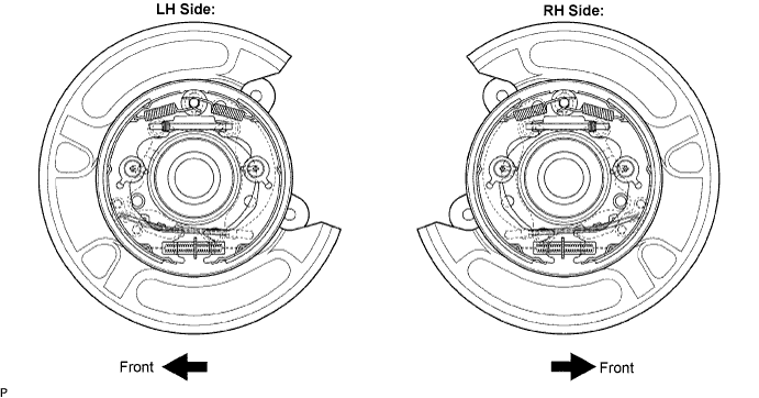
- NOTICE:
- There should be no oil or grease adhering to the friction surfaces of the shoe lining or the disc.
| 9.
INSTALL REAR DISC
|
|
Align the matchmarks of the disc and axle hub and install the disc.
| 10.
ADJUST PARKING BRAKE SHOE CLEARANCE
|
|
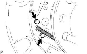
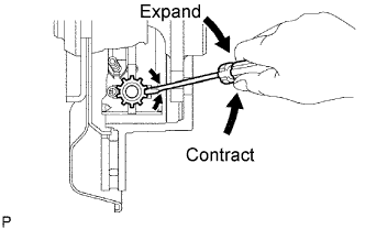
Provisionally install the 2 hub nuts.
Remove the hole plug, and turn the adjuster to expand the shoe until the disc locks.
Contract the shoe adjuster until the disc rotates smoothly.
- Standard:
- Return 8 notches
Install the hole plug.
| 11.
INSTALL REAR DISC BRAKE CALIPER ASSEMBLY
|
|
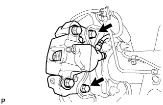
Install the disc brake caliper with the 2 bolts and 2 washers.
-
Torque:
- 105 N*m{
1,071 kgf*cm
, 78 ft.*lbf
}
| 12.
INSTALL REAR WHEEL |
|
-
Torque:
- 112 N*m{
1,137 kgf*cm
, 82 ft.*lbf
}
| 13.
INSPECT PARKING BRAKE LEVER TRAVEL
|
|
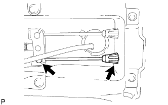
Slowly pull the parking brake lever to the fully applied position, counting the number of clicks.
- Parking brake lever travel:
- 5 to 7 clicks at 200 N (20 kgf, 45 lbf)
| 14.
ADJUST PARKING BRAKE LEVER TRAVEL
|
|
Turn the adjusting nut until the parking brake lever travel is corrected to within the specified range.
- Parking brake lever travel:
- 5 to 7 clicks at 200 N (20 kgf, 45 lbf)
Operate the parking brake lever 3 to 4 times, and check the parking brake lever travel.
Check whether the parking brake drags or not.
When operating the parking brake lever, check that the brake warning light illuminates.
- Standard:
- Brake warning light always illuminates at the first click.
| 15.
INSTALL FRONT CONSOLE BOX
|
|
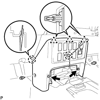
- Engage the 3 clips and 2 claws and install the instrument lower cover.
Install the 2 <F> bolts and 2 clips.
| 16.
INSTALL BOX BOTTOM MAT
|
|
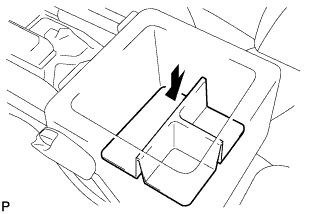
- Install the box bottom mat.
| 17.
INSTALL CONSOLE UPPER REAR PANEL SUB-ASSEMBLY
|
|
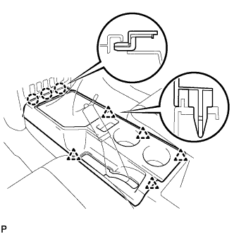
- Engage the 3 claws and 5 clips and install the console upper rear panel.
| 18.
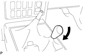
INSTALL SHIFT LEVER KNOB SUB-ASSEMBLY
|
|
- Install the shift lever knob.
| 19.
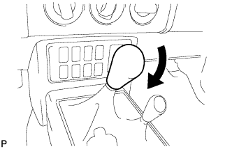
INSTALL SHIFT LEVER KNOB SUB-ASSEMBLY (for Manual Transmission)
|
|
- Install the shift lever knob.
| 20.
INSTALL PARKING BRAKE HOLE COVER SUB-ASSEMBLY
|
|
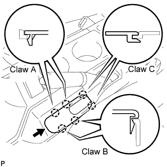
Slide the parking brake hole cover toward the rear of the vehicle and engage the 2 C claws.
Engage the 4 claws and install the parking brake hole cover.