WINDSHIELD GLASS > INSTALLATION |
| 1. CLEAN WINDSHIELD GLASS |
|
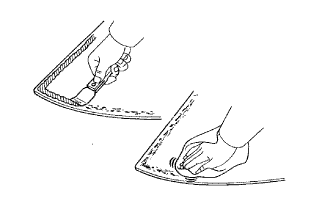
Using a scraper, remove the damaged stoppers, dam and adhesive from the windshield glass.
Clean the outer circumference of the windshield glass with a non-residue solvent.
| 2. CLEAN VEHICLE BODY |
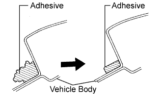 |
Clean and shape the contact surface of the vehicle body.
Using a knife, cut away any rough adhesive on the contact surface of the vehicle body to ensure the appropriate surface shape.
Clean the contact surface of the vehicle body with a shop rag or piece of cloth saturated with cleaner.
| 3. INSTALL WINDSHIELD GLASS STOPPER NO. 1 |
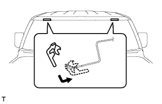 |
Install 2 new stoppers onto the vehicle body, as shown in the illustration.
| 4. INSTALL WINDSHIELD GLASS STOPPER NO. 2 |
 |
Apply Primer G to the installation parts of the stoppers.
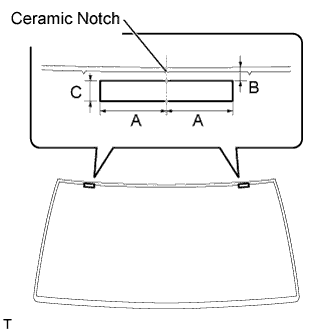
Install 2 new stoppers onto the windshield glass, as shown in the illustration.
| Area | Measurement |
| A | 40 mm (1.57 in.) |
| B | 7.8 mm (0.307 in.) |
| C | 12.5 mm (0.482 in.) |
| 5. INSTALL WINDSHIELD OUTSIDE MOULDING |
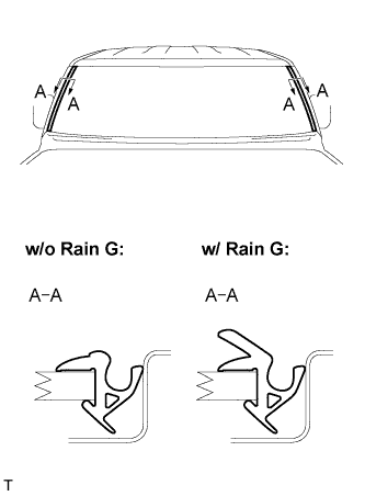 |
Using a brush or sponge, coat the edge of the glass and the contact surface with Primer G.
Install the moulding onto the windshield glass, as shown in the illustration.
| 6. INSTALL WINDOW GLASS ADHESIVE DAM |
Apply Primer G to the installation parts of new dams.
Install 3 new dams by applying double-sided tape all the way around the windshield glass except where the stoppers are installed, as shown in the illustration.
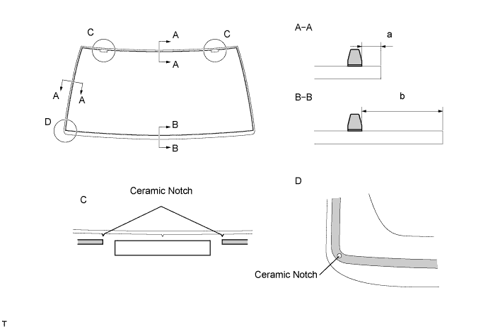
| Area | Measurement |
| a | 7.0 mm (0.276 in.) |
| b | 15.8 mm (0.622 in.) |
| 7. INSTALL WINDSHIELD GLASS |
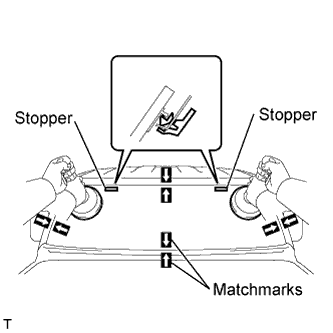 |
Position the windshield glass.
Using suction cups, place the windshield glass in the correct position.
Check that the entire contact surface of the windshield glass rim is perfectly even.
Place matchmarks on the windshield glass and vehicle body.
Using suction cups, remove the windshield glass.
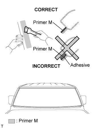 |
Using a brush, apply Primer M to the exposed part of the vehicle body.
Using a brush or sponge, apply Primer G to the edge of the windshield glass and the contact surface.
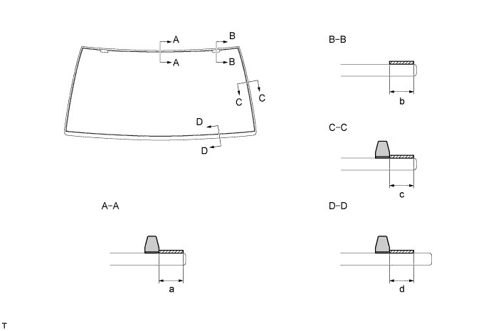
| Area | Measurement |
| a | 7.8 mm (0.307 in.) |
| b | 7.8 mm (0.307 in.) |
| c | 7.0 mm (0.276 in.) |
| d | 8.0 mm (0.315 in.) |
Apply adhesive.
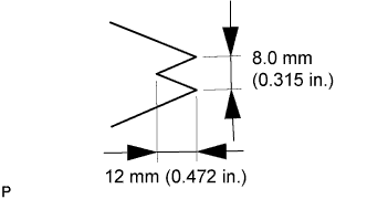 |
Cut the tip off the cartridge nozzle, as shown in the illustration.
| Temperature | Usage Time Frame |
| 35°C (95°F) | 15 minutes |
| 20°C (68°F) | 1 hour 40 minutes |
| 5°C (41°F) | 8 hours |
Load the sealer gun with the cartridge.
Apply adhesive to the windshield glass, as shown in the illustration.
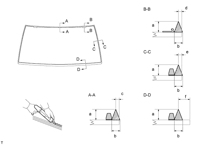
| Area | Measurement |
| a | 12 mm (0.472 in.) |
| b | 8 mm (0.315 in.) |
| c | 3 mm (0.118 in.) |
| d | 3 mm (0.118 in.) |
| e | 3 mm (0.118 in.) |
| f | 11.8 mm (0.465 in.) |
|
Install the windshield glass onto the vehicle body.
Using suction cups, position the windshield glass so that the matchmarks are aligned. Gently press it in along the rim.
Gently press the front surface of the windshield glass to ensure that the windshield glass is securely fitted to the vehicle body.
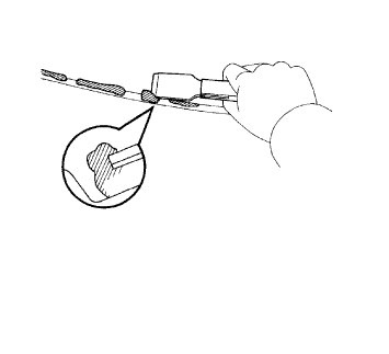 |
Using a scraper, remove any excessive or protruding adhesive.
| Temperature | Minimum time prior to driving vehicle |
| 35°C (95°F) | 1 hour 30 minutes |
| 20°C (68°F) | 5 hours |
| 5°C (41°F) | 24 hours |
| 8. INSTALL WINDSHIELD OUTSIDE LOWER MOULDING |
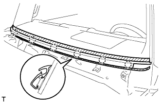 |
Engage the 6 claws and install the windshield outside lower moulding.
| 9. CHECK FOR LEAKAGE AND REPAIR |
Conduct a leak test by applying water to the adhesive portions after the adhesive has completely hardened.
Seal any leakage with auto glass sealer.
| 10. INSTALL ROOF SIDE GARNISH PROTECTOR |
Install a new roof side garnish protector with the 4 clips.
| 11. INSTALL FRONT PILLAR OUTER GARNISH |
Engage the 5 clips and install the front pillar outer garnish.
Tighten the nut.
| 12. INSTALL ROOF DRIP SIDE FINISH MOULDING RETAINER |
Install the roof drip side finish moulding retainer.
| 13. INSTALL WINDSHIELD OUTSIDE UPPER MOULDING SUB-ASSEMBLY |
Clean the windshield glass.
Using a scraper, remove the adhesive from the windshield glass.
Clean the outer circumference of the windshield glass with a non-residue solvent.
Using a brush or sponge, apply Primer G to the contact surface.
Apply adhesive.
Cut the tip off the cartridge nozzle.
| Temperature | Usage Time Frame |
| 35°C (95°F) | 15 minutes |
| 20°C (68°F) | 1 hour 40 minutes |
| 5°C (41°F) | 8 hours |
Load the sealer gun with the cartridge.
Apply adhesive to a new windshield outside upper moulding, as shown in the illustration.
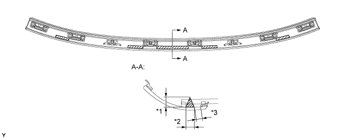
| Area | Measurement |
| *1 | 10 mm (0.394 in.) or more |
| *2 | 8 mm (0.315 in.) or more |
| *3 | 3.5 to 9.5 mm (0.138 to 0.374 in.) |
Engage the 4 claws and the 2 clips and install a new windshield outside upper moulding.
| Temperature | Minimum time prior to driving vehicle |
| 35°C (95°F) | 1 hour 30 minutes |
| 20°C (68°F) | 5 hour |
| 5°C (41°F) | 24 hours |
Remove the protective tape.
| 14. INSTALL ROOF HEADLINING |
| 15. INSTALL PERSONAL LIGHT ASSEMBLY (w/ CRAWL) |
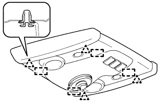 |
Install the 4 new clips to the personal light assembly.
Connect the connector.
Engage the 4 clips and 4 guides to install the personal light assembly.
| 16. INSTALL ROOM LIGHT ASSEMBLY |
Install room light bulb No. 1.
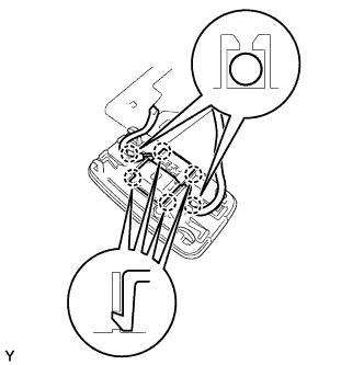 |
Engage the 4 claws and install the room light switch base.
Install the roof wire into the claw of the room light.
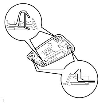 |
Engage the 4 claws and install the room light.
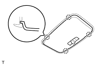 |
Engage the 4 claws and install the room light lens.
| 17. INSTALL INNER REAR VIEW MIRROR ASSEMBLY |
| 18. INSTALL VISOR HOLDER |
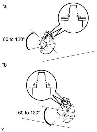 |
| *a | for RH Side |
| *b | for LH Side |
Engage the 2 claws by turning the visor holder clockwise between 60 to 120° and install the visor holder.
| 19. INSTALL VISOR ASSEMBLY RH |
Install the visor with the 2 screws.
Install the visor support shaft into the visor holder.
| 20. INSTALL VISOR ASSEMBLY LH |
| 21. INSTALL FRONT PILLAR GARNISH RH |
Engage the guide and the 2 clips and install the front pillar garnish.
| 22. INSTALL FRONT PILLAR GARNISH LH |
| 23. INSTALL VISOR SUB-ASSEMBLY RH |
Engage the 2 claws and install the visor sub-assembly.
| 24. INSTALL VISOR SUB-ASSEMBLY LH |
| 25. INSTALL ASSIST GRIP ASSEMBLY |
Install the assist grip with the 2 bolts.
| 26. INSTALL ASSIST GRIP PLUG |
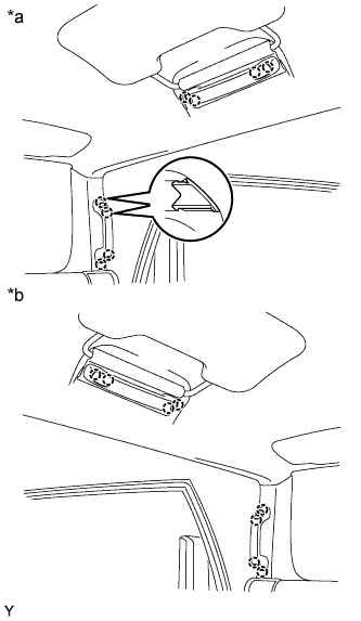 |
| *a | for RH Side |
| *b | for LH Side |
Engage the 2 claws and install the assist grip plug.
| 27. INSTALL FRONT DOOR OPENING TRIM WEATHERSTRIP RH |
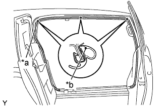 |
Align the locating marks with the paint marks first, and install the front door opening trim weatherstrip, as shown in the illustration.
| *a | Locating Mark |
| *b | Paint Mark |
| Area | Color |
| RH side | White |
| LH side | Red |
| 28. INSTALL FRONT DOOR OPENING TRIM WEATHERSTRIP LH |
| 29. INSTALL ROOF SIDE RAIL GARNISH RH |
Engage the claw and the guide install the roof side rail garnish.
Install the 2 bolts.
| 30. INSTALL ROOF SIDE RAIL GARNISH LH |
| 31. INSTALL ROOF SIDE INNER GARNISH COVER RH |
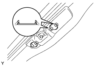 |
Engage the 2 claws and install the roof side inner garnish cover.
| 32. INSTALL ROOF SIDE INNER GARNISH COVER LH |
| 33. INSTALL COWL SIDE TRIM BOARD RH |
Engage the 2 claws and install the cowl side trim board.
Install the clip.
| 34. INSTALL COWL SIDE TRIM BOARD LH |
| 35. INSTALL FOOTREST CLIP |
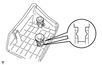 |
Engage the 2 claws and install the footrest clip.
| 36. INSTALL FRONT FLOOR FOOTREST |
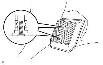 |
Engage the 2 studs and install the front floor footrest.
| 37. INSTALL ACCESS DOOR SCUFF PLATE RH |
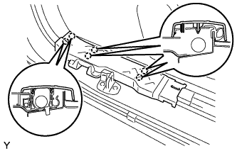 |
Engage the 6 claws and install the access door scuff plate.
| 38. INSTALL ACCESS DOOR SCUFF PLATE LH |
| 39. INSTALL FRONT DOOR SCUFF PLATE RH |
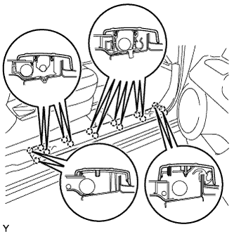 |
Engage the 14 claws and install the door scuff plate.
| 40. INSTALL FRONT DOOR SCUFF PLATE LH |
| 41. INSTALL COWL TOP VENTILATOR LOUVER LH |
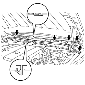 |
Install the cowl top ventilator louver LH with the 5 clips and engage the 7 claws.
| 42. INSTALL COWL TOP VENTILATOR LOUVER RH |
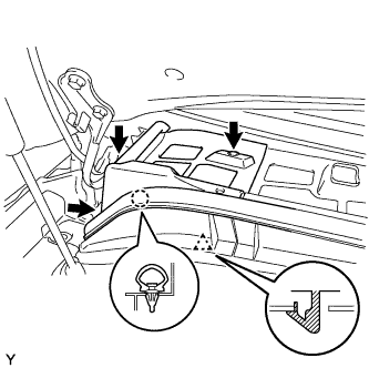 |
Install the cowl top ventilator louver RH with the 3 clips and the claw.
Install the hood to cowl top seal with the clip.
| 43. INSTALL COWL TOP VENTILATOR LOUVER SUB-ASSEMBLY |
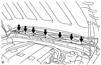 |
Install the cowl top ventilator louver sub-assembly with the 7 clips.
| 44. INSTALL FRONT FENDER SIDE PANEL UPPER LH |
Install the 4 new clips on the front fender side panel upper LH.
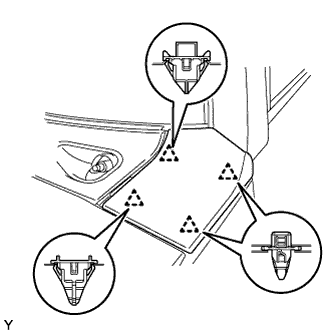 |
Engage the 4 clips and install the front fender side panel upper LH.
| 45. INSTALL FRONT FENDER SIDE PANEL UPPER RH |
Install the 4 new clips on the front fender side panel upper RH.
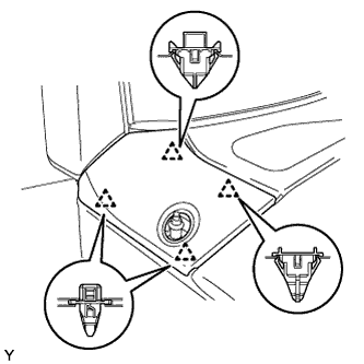 |
Engage the 4 clips and install the front fender side panel upper RH.
| 46. INSTALL ANTENNA ORNAMENT |
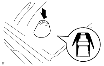 |
Press in the antenna ornament in the direction shown in the illustration.
| 47. INSTALL ROOF ANTENNA POLE SUB-ASSEMBLY |
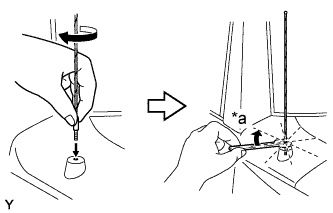 |
Install the radio antenna pole sub-assembly by hand until fully seated.
| *a | 1/8 turn (20 to 45 degrees) |
Using a 8 mm (5/16 inch) wrench, fully tighten the radio antenna pole about 1/8 turn (20 to 45 degrees) by turning it clockwise.
| 48. INSTALL FRONT WIPER ARM AND BLADE ASSEMBLY LH |
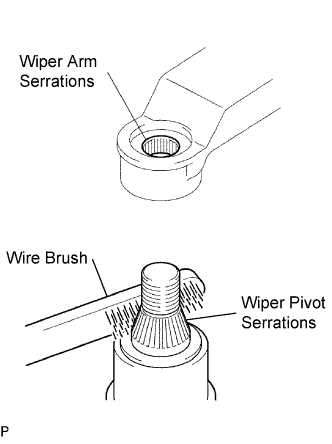 |
Scrape any metal powder off the serrated part of the wiper arm with a round file or the equivalent (when reinstalling).
Clean the wiper pivot serrations with a wire brush.
Operate the wiper, then stop the windshield wiper motor in the automatic stop position.
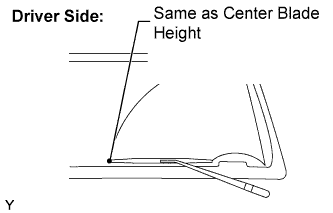 |
Align the blade tip with the mark on the windshield glass, as shown in the illustration.
Tighten the nut of the front wiper arm.
| 49. INSTALL FRONT WIPER ARM AND BLADE ASSEMBLY RH (CENTER SIDE) |
|
Scrape any metal powder off the serrated part of the wiper arm with a round file or the equivalent (when reinstalling).
Clean the wiper pivot serrations with a wire brush.
Operate the wiper, then stop the windshield wiper motor in the automatic stop position.
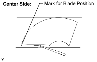 |
Align the blade tip with the mark on the windshield glass, as shown in the illustration.
Tighten the nut of the front wiper arm.
| 50. INSTALL FRONT WIPER ARM AND BLADE ASSEMBLY RH |
|
Scrape any metal powder off the serrated part of the wiper arm with a round file or the equivalent (when reinstalling).
Clean the wiper pivot serrations with a wire brush.
Operate the wiper, then stop the windshield wiper motor in the automatic stop position.
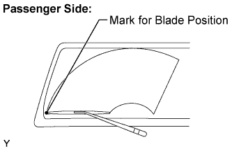 |
Align the blade tip with the mark on the windshield glass, as shown in the illustration.
Tighten the nut of the front wiper arm.
| 51. INSTALL WINDSHIELD WIPER ARM COVER |
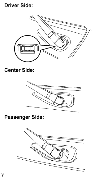 |
Engage the claw and install the 3 front wiper arm cover.
| 52. CONNECT CABLE TO NEGATIVE BATTERY TERMINAL |