AIR CONDITIONING UNIT > INSPECTION |
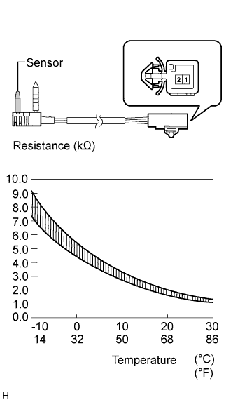
| 1. INSPECT NO. 1 COOLER THERMISTOR |
|
Measure the resistance.
| Tester Connection | Condition | Specified Condition |
| 1 - 2 | -10°C (14°F) | 7.30 to 9.10 kΩ |
| 1 - 2 | -5°C (23°F) | 5.65 to 6.95 kΩ |
| 1 - 2 | 0°C (32°F) | 4.40 to 5.35 kΩ |
| 1 - 2 | 5°C (41°F) | 3.40 to 4.15 kΩ |
| 1 - 2 | 10°C (50°F) | 2.70 to 3.25 kΩ |
| 1 - 2 | 15°C (59°F) | 2.14 to 2.58 kΩ |
| 1 - 2 | 20°C (68°F) | 1.71 to 2.05 kΩ |
| 1 - 2 | 25°C (77°F) | 1.38 to 1.64 kΩ |
| 1 - 2 | 30°C (86°F) | 1.11 to 1.32 kΩ |
| 2. INSPECT MODE CONTROL SERVO MOTOR |
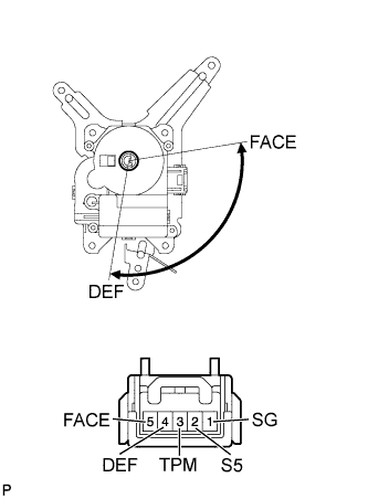 |
Inspect the servo motor operation.
Connect the positive (+) lead from the battery to terminal 4 (DEF) and negative (-) lead to terminal 5 (FACE), then check that the lever turns to the DEF position smoothly.
Connect the positive (+) lead from the battery to terminal 5 (FACE) and negative (-) lead to terminal 4 (DEF), then check that the lever turns to the FACE position smoothly.
Check the servo motor resistance.
Using an ohmmeter, measure the resistance and check the results in accordance with the values in the table below.
| Tester Connection | Servo Motor Position | Specified Condition |
| 1 (SG) - 2 (S5) | Always | 4.2 to 7.8 kΩ |
| 1 (SG) - 3 (TPM) | DEF Position | 3.4 to 6.2 kΩ |
| 1 (SG) - 3 (TPM) | FACE Position | 0.8 to 1.6 kΩ |
| 3. REMOVE AIR MIX CONTROL SERVO MOTOR |
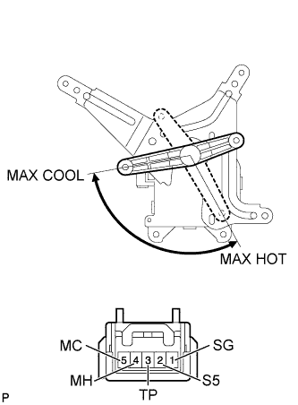 |
Inspect the servo motor operation.
Connect the positive (+) lead from the battery to terminal 4 (MH) and negative (-) lead to terminal 5 (MC), then check that the lever turns to the MAX HOT position smoothly.
Connect the positive (+) lead from the battery to terminal 5 (MC) and negative (-) lead to terminal 4 (MH), then check that the lever turns to the MAX COOL position smoothly.
Check the servo motor resistance.
Using an ohmmeter, measure the resistance and check the results in accordance with the values in the table below.
| Tester Connection | Servo Motor Position | Specified Condition |
| 1 (SG) - 2 (S5) | Always | 4.2 to 7.8 kΩ |
| 1 (SG) - 3 (TP) | MAX HOT Position | 3.4 to 6.2 kΩ |
| 1 (SG) - 3 (TP) | MAX COOL Position | 0.8 to 1.6 kΩ |