Home › COMMUNICATION SYSTEM › MULTIPLEX COMMUNICATION › MULTIPLEX COMMUNICATION SYSTEM

MULTIPLEX COMMUNICATION SYSTEM > TERMINALS OF ECU

for Preparation Click here


CHECK MAIN BODY ECU


  1. Disconnect the 1B, 1E, 1F, 1L and E6 main body ECU connectors.
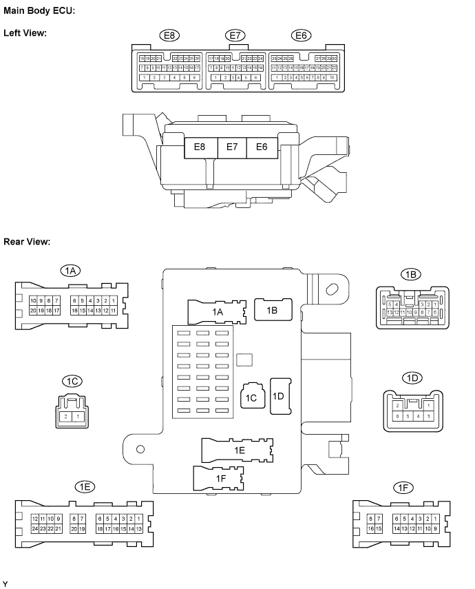
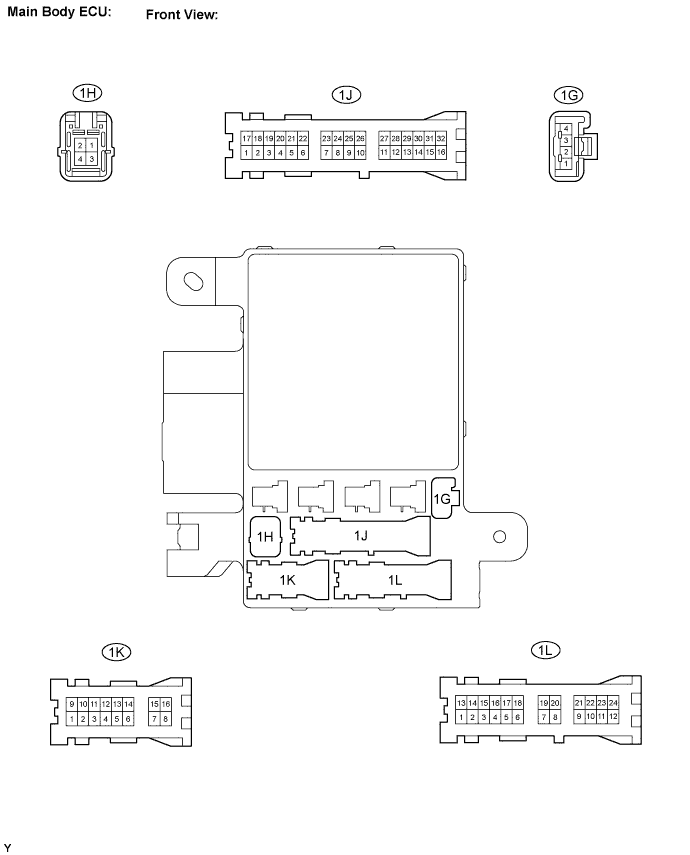
    B136051E02


    B136052E02

  2. Measure the voltage of the wire harness side connectors.

    Standard voltage: 
    Symbols (Terminals No.)
    Wiring Color
    Terminal Description
    Condition
    Specified Condition
    1B-4 (BECU) - Body ground
    W-R - Body ground
    Power source (+B)
    Always
    11 to 14 V
    1L-4 (BECU) - Body ground
    W-R - Body ground
    Power source (+B)
    Always
    11 to 14 V
    1F-12 (BECU) - Body ground
    W-R - Body ground
    Power source (+B)
    Always
    11 to 14 V
    1E-9 (BDR1) - Body ground
    B-Y - Body ground
    Power source (+B)
    Always
    11 to 14 V
    E6-23 (MPX2) - Body ground
    BR-R - Body ground
    Multiplex communication signal
    During communication
    Signal waveform
    If the result is not as specified, there may be a malfunction on the wire harness side.


CHECK BACK DOOR ECU


  1. Disconnect the S2 ECU connector.


    B062706E01

  2. Measure the voltage of the wire harness side connector.

    Standard voltage: 
    Symbols (Terminals No.)
    Wiring Color
    Terminal Description
    Condition
    Specified Condition
    S2-3 (GND) - Body ground
    W-B - Body ground
    Ground for main power supply
    Ground for main power supply
    Below 1 V
    S2-5 (BECU) - S2-3 (GND)
    W-R - W-B
    Power source (+B)
    Always
    11 to 14 V
    S2-4 (BDR) - S2-3 (GND)
    L-O - W-B
    Power source (+B)
    Always
    11 to 14 V
    S2-1 (MPX2) - Body ground
    BR-R - Body ground
    Multiplex communication signal
    During communication
    Signal waveform
    S2-6 (SIG) - Body ground
    B-R - Body ground
    Power source (IG)
    Ignition switch ON
    11 to 14 V
    If the result is not as specified, there may be a malfunction on the wire harness side.