Home › RESTRAINTS › SUPPLEMENTAL RESTRAINT SYSTEM › AIRBAG SYSTEM

AIRBAG SYSTEM > DIAGNOSIS SYSTEM

for Preparation Click here


SYMPTOM SIMULATION

HINT:
The most difficult case in troubleshooting is when no symptoms occur. In such cases, a thorough customer problem analysis must be carried out. Then the same or similar conditions and environment in which the problem occurred in the customer's vehicle should be simulated. No matter how experienced or skilled a technician may be, if he proceeds to troubleshoot without confirming the problem symptoms, he will likely overlook something important and make a wrong guess at some points in the repair operation.
This leads to a standstill in troubleshooting.


    H100146E01
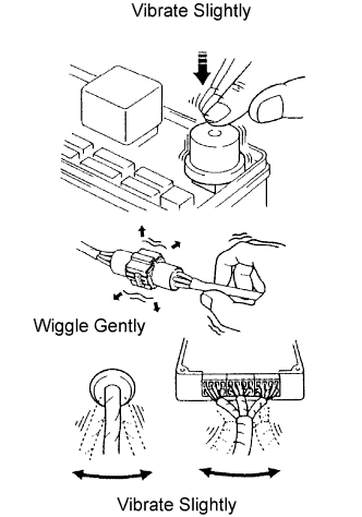
  1. Simulation method: When vibration seems to be the major cause

    HINT:
    Perform this method only during the primary check period (for approximately 6 seconds after the ignition switch is turned to ON).


    1. Use your finger to slightly vibrate the part of the sensor considered to be the problem cause, and check whether the malfunction recurs.

      HINT:
      Wiggling the relays too strongly may result in open relays.

    2. Gently wiggle the connector.

    3. Slightly shake the wire harness vertically and horizontally.
      The connector joint and fulcrum of the vibration are the major areas to be checked thoroughly.

FUNCTION OF SRS WARNING LIGHT
  1. Primary check

    1. Turn the ignition switch off. Wait for at least 2 seconds, then turn the ignition switch to ON. The SRS warning light comes on for approximately 6 seconds and the SRS airbag system diagnosis (including the seat belt pretensioner) is performed.

      HINT:
      If any malfunctions are detected during the primary check, the SRS warning light remains on even after the primary check period has elapsed.

  2. Constant check

    1. After the primary check, the center airbag sensor assembly constantly monitors the SRS airbag system for trouble.

      HINT:
      If any malfunctions are detected during the constant check, the center airbag sensor assembly functions as follows:
      1. The SRS warning light comes on.
      2. The SRS warning light goes off, and then comes on again. This blinking pattern indicates a source voltage drop. The SRS warning light goes off 10 seconds after the source voltage returns to normal.

  3. Review

    1. When the airbag system is normal:
      The SRS warning light comes on only during the primary check period (for approximately 6 seconds after the ignition switch is turned to ON).

    2. When the airbag system malfunctions:

      1. The SRS warning light blinks after the primary check period has elapsed.
      2. The SRS warning light goes off after the primary check, but comes on again during the constant check.
      3. The SRS warning light remains off even after the ignition switch is turned from off to ON. However, if malfunctions such as an open circuit have occurred in the wire harness between the meter and the center airbag sensor assembly, the warning light comes on 10 seconds after the ignition switch is turned to ON.

      HINT:
      The center airbag sensor assembly keeps the SRS warning light on if any malfunctions have been detected in the airbag system.


SRS WARNING LIGHT CHECK
  1. Turn the ignition switch to ON, and check that the SRS warning light comes on for approximately 6 seconds (primary check).

  2. Check that the SRS warning light goes off approximately 6 seconds after the ignition switch is turned to ON (constant check).

    HINT:
    When any of the following symptoms occur, refer to the Problem Symptoms Table (Click here).
    1. The SRS warning light comes on occasionally, after the primary check period has elapsed.
    2. Even when the SRS warning light comes on, no DTCs are set.
    3. Even when the ignition switch is turned from off to ON, the SRS warning light remains off.


FUNCTION OF SRS CONNECTORS


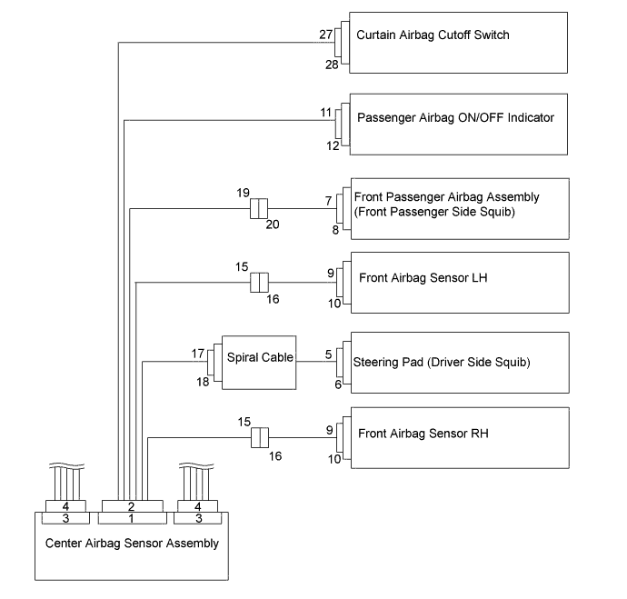
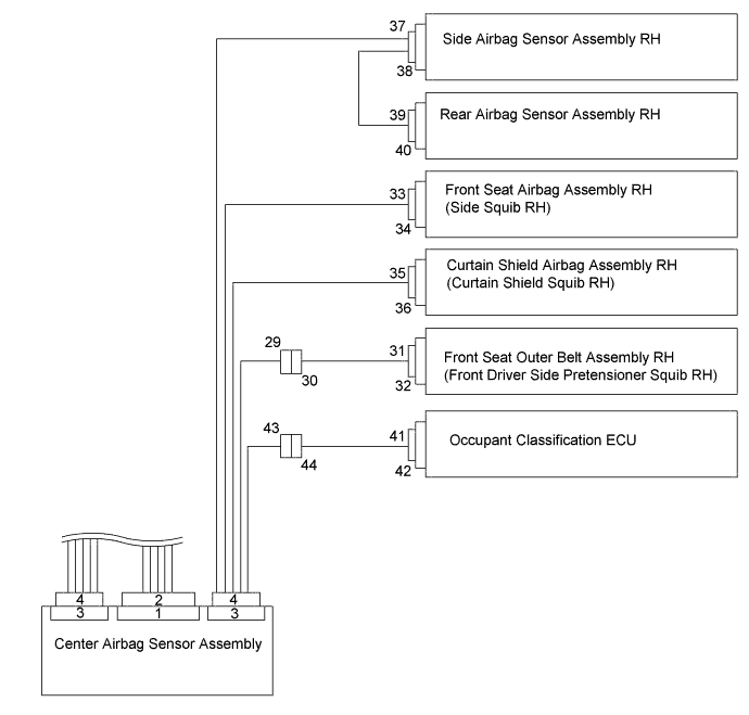
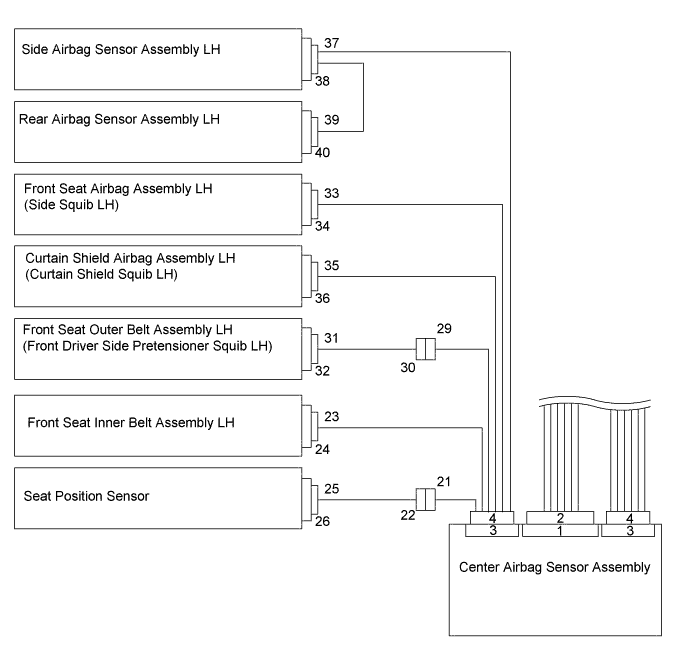
  1. SRS connectors are located as shown in the following illustration.


    C268876E01


    C268877E01


    C268878E01


    Item
    Application
    Terminal Twin-Lock Mechanism
    Connectors 11, 15, 16, 17, 19, 20, 25, 30, 33, 36, 37, 39
    Half Connection Prevention Mechanism
    Connectors 9, 15, 17, 19, 21, 29, 33, 35
    Activation Prevention Mechanism
    Connectors 2, 4, 6, 8, 18, 20, 30, 32, 34, 36
    Connector Lock Mechanism (1)
    Connectors 5, 7, 31
    Connector Position Assurance Mechanism
    Connector 37, 39
    Connector Lock Mechanism (2)
    Connectors 2, 4
    Improper Connection Prevention Lock Mechanism
    Connectors 1, 3


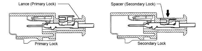
  2. Terminal twin-lock mechanism


    C190972E01


    1. This mechanism is designed to increase the ability of the terminal to remain connected and prevent it from accidentally being disconnected.

    2. The connector has a two-piece construction consisting of the housing and spacer to securely lock the terminal using both the lance (primary lock) and spacer (secondary lock).


  3. Half connection prevention mechanism


    C147461E08


    1. This mechanism is designed to prevent the connector from being connected only halfway.

    2. If the connector is not completely connected, the connector is disconnected due to the spring force so that no continuity exists.


  4. Activation prevention mechanism


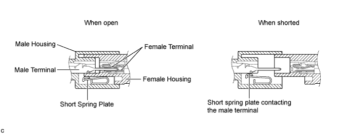
    C238382E01


    1. The activation prevention mechanism is designed to create a short circuit automatically between the positive and negative terminals of an airbag power source connector when disconnected.

    2. The short spring plate contained in the connector creates a closed circuit on the airbag side (no potential difference can occur between both terminals), preventing accidental airbag deployment when servicing.


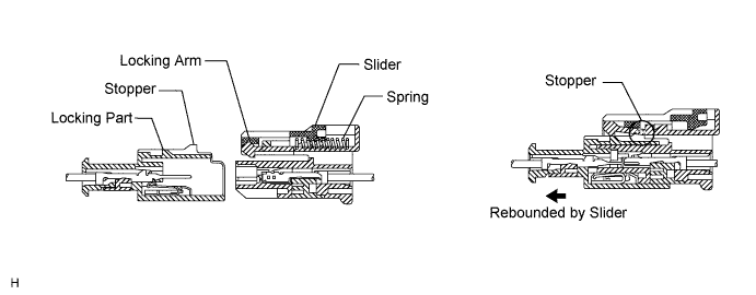
  5. Connector lock mechanism (1)


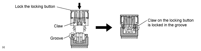
    C147462E01


    1. This mechanism is designed to prevent the connector from accidentally being disconnected.

    2. Locking the connector lock button engages the locking button claw to the groove on the other side connector to connect the connector securely.


  6. Connector Position Assurance (CPA) mechanism


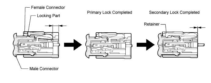
    C161464E01


    1. This mechanism is designed to detect when the connector is connected only halfway.

    2. The CPA and female connector slide to the male connector side at the same time and the primary lock is completed when the female connector is engaged with the male connector. From this point, only the CPA slides to the male connector side and secondary lock is completed when the CPA retainer is engaged with the female connector. When the CPA and female connector ends are aligned, they are completely engaged.


  7. Connector lock mechanism (2)


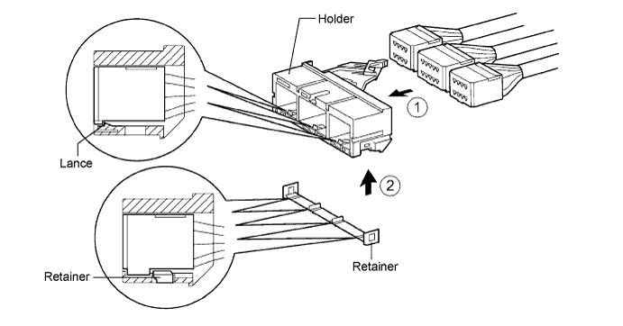
    H043918E06


    1. This mechanism is designed to prevent the connector from accidentally being disconnected.

    2. Sliding the connector all the way into the holder and locking the lance completes the primary lock.

    3. Engaging the retainer to the holder as shown in the illustration completes the secondary lock, preventing the connector from accidentally being disconnected.


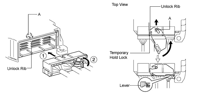
  8. Improper connection prevention lock mechanism


    C204952E03


    1. This mechanism is designed to prevent the connector from being connected only halfway.

    2. When the holder is connected to the airbag sensor assembly, the unlock rib unlocks the temporary hold lock, allowing the lever to be pushed in by rotating around the axis A.

    3. Locking the lever to the holder locks the holder securely.


ACTIVATION PREVENTION MECHANISM
  1. Function of activation prevention mechanism

    1. An activation prevention mechanism is built into the connector (on the airbag sensor assembly side) of the airbag system squib circuit to prevent accidental airbag activation.

    2. This mechanism closes the circuit when the connector is disconnected by bringing the short spring into contact with the terminals and insulating the circuit from external power sources to prevent accidental airbag activation.


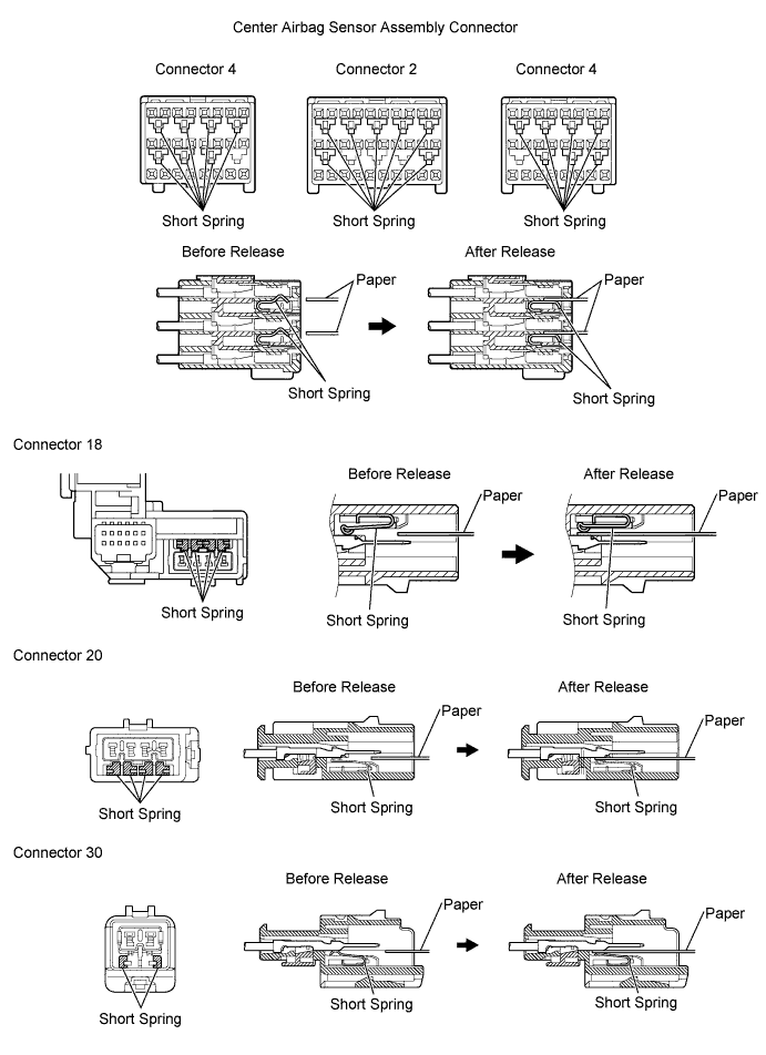
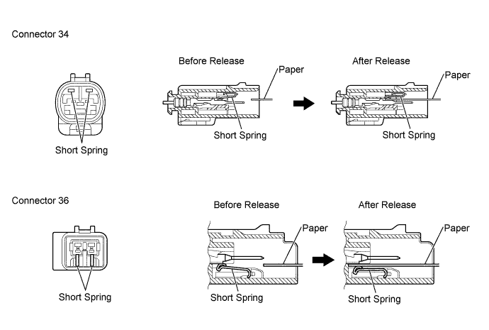
  2. Releasing of activation prevention mechanism

    1. To release the activation prevention mechanism, insert a piece of paper with the same thickness as the male terminal (approximately 0.5 mm (0.0197 in.)) between the terminals and short spring to break the connection.


    2. Refer to the following illustrations concerning connectors utilizing the activation prevention mechanism and its release method.

      CAUTION:
      Never release the activation prevention mechanism on the squib connector even when inspecting with the squib disconnected.

      NOTICE:
      1. Do not release the activation prevention mechanism unless specially directed by the troubleshooting procedure.
      2. To prevent the terminal and short spring from being damaged, always use a piece of paper with the same thickness as the male terminal.


      C190137E04


      C192773E03