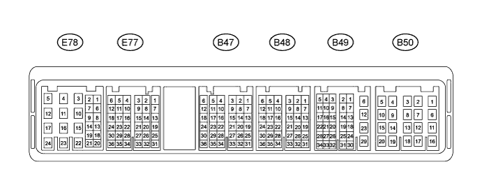
Disconnect the E32 and E33 connectors from the air conditioning amplifier assembly and inspect the connector on the wire harness side, as shown in the table below.
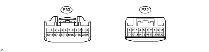
| Symbols (Terminals No.) | Wiring Colors | Terminal Descriptions | Conditions | Specified Condition |
| IG+ (E32-1) - GND (E32-20) | Y-R - W-B | Power source (IG) | Ignition switch: OFF → ON | Below 1.0 → 11 to 14 V |
| B (E32-11) - GND (E32-20) | W-R - W-B | Power source (Back-up) | Always | 11 to 14 V |
| SG-1 (E33 - 17) - Body ground | V-G - Body ground | Ground for mode control servo motor | Always | Below 1.0 Ω |
| SG-2 (E33 - 18) - Body ground | Y-G - Body ground | Ground for air mix control servomotor | Always | Below 1.0 Ω |
| SG-3 (E33 - 6) - Body ground | G-Y - Body ground | Ground for lock sensor | Always | Below 1.0 Ω |
| SG-4 (E32 - 9) - Body ground | GR-R - Body ground | Ground for A/C evaporator temperature sensor | Always | Below 1.0 Ω |
| TAMG (E33 - 16) - Body ground | GR - Body ground | Ground for ambient temperature sensor | Always | Below 1.0 Ω |
| GND (E32-20) - Body ground | W-B - Body ground | Ground for main power supply | Always | Below 1.0 Ω |
Reconnect the E32 and E33 connectors to the air conditioning amplifier assembly and inspect the wire harness side connector from the back side, as shown in the table below.
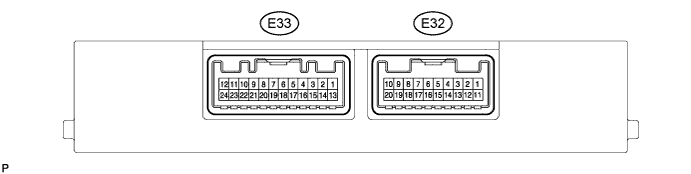
| Symbols (Terminals No.) | Wiring Colors | Terminal Descriptions | Conditions | Specified Condition |
| DEF (E33-9) - GND (E32-20) | LG - W-B | Mode switch signal | Ignition switch: ON Mode select switch: Except DEF → DEF | Below 1.5 → 11 to 14 V |
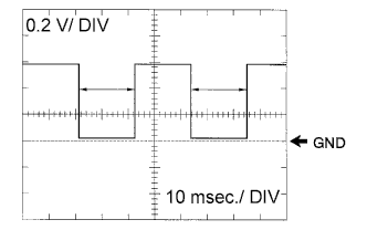
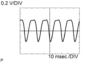
| LOCK (E33-8) - SG-3 (E33-6) | R-W - G-Y | Magnet clutch signal | Start engine Operate A/C system Magnet clutch: ON | Pulse generation (See waveform 1) |
| AC1 (E33-24) - GND (E32-20) | G-W - W-B | Idle up request signal | Engine idling Operate A/C system Magnet clutch: OFF → ON | 11 to 14 → Below 1.0 V |
| FRS (E32-6) - GND (E32-20) | V - W-B | Recirculation/Fresh switch signal | Ignition switch: ON Recirculation/Fresh switch: RECIRCULATION → FRESH | 11 to 14 → Below 1.0 V |
| REC (E32-7) - GND (E32-20) | P-B - W-B | Recirculation/Fresh switch signal | Ignition switch: ON Recirculation/Fresh switch: FRESH → RECIRCULATION | 11 to 14 → Below 1.0 V |
| MGC (E32-4) - GND (E32-20) | LG-B - W-B | Magnet clutch relay signal | Engine idling Operate A/C system Magnet clutch: OFF → ON | 11 to 14 → Below 1.0 V |
| PSW (E33-22) - GND (E32-20) | LG-R - W-B | A/C pressure switch signal | Start engine Operate A/C system Refrigerant pressure: Normal (Less than 196 kPa (2.0 kgf/cm2, 28 psi)) or more than 3140 kPa (32.0 kgf/cm2, 455 psi)) | 11 to 14 → Below 1.0 V |
| BLW (E32-8) - GND (E32-20) | Y - W-B | Blower switch signal | Ignition switch: ON Blower switch: ON OFF → ON (LO, M1, M2, HI) | 11 to 14 → Below 1.0 V |
| TE (E32-10) - SG-4 (E32-9) | B - GR-R | A/C evaporator temperature sensor signal | Ignition switch: ON Evaporator temperature: 0 → 15°C (32 → 59°F) | 1.7 to 2.1 → 0.9 to 1.3 V |
| TAM (E33-13) - TAMG (E33-16) | Y - GR | Ambient temperature sensor signall | Ignition switch: ON Ambient temperature: 25 → 40°C (77 → 104°F) | 1.7 to 2.1 → 1.3 to 1.8 V |
| RDFG (E32-5) - GND (E32-20) | Y-V - W-B | Defogger switch signal | Ignition switch: ON Defogger switch: OFF → ON | 11 to 14 → Below 1.0 V |
| S5 (E33-19) - SG-1 (E33-17) | P - V-G | Power supply for mode control servo motor | Ignition switch: OFF → ON | 0 to 5.0 V |
| S5-1 (E33-7) - SG-2 (E33-18) | P-B - Y-G | Power supply for air mix control servomotor | Ignition switch: OFF → ON | 0 to 5.0 V |
| SG-1 (E33-17) - Body ground | V-G - Body ground | Ground for mode control servo motor | Always | Below 1.0 Ω |
| SG-2 (E33-18) - Body ground | Y-G - Body ground | Ground for air mix control servomotor | Always | Below 1.0 Ω |
| SG-3 (E33-6) - Body ground | G-Y - Body ground | Ground for lock sensor | Always | Below 1.0 Ω |
| SG-4 (E32-9) - Body ground | GR-R - Body ground | Ground for A/C evaporator temperature sensor | Always | Below 1.0 Ω |
| TAMG (E33-16) - Body ground | GR - Body ground | Ground for ambient temperature sensor | Always | Below 1.0 Ω |
| GND (E32-20) - Body ground | W-B - Body ground | Ground for main power supply | Always | Below 1.0 Ω |
| IG+ (E32-1) - Body ground | Y-R - Body ground | Power source (IG) | Ignition switch: OFF → ON | Below 1.0 → 11 to 14 V |
| B (E32-11) - Body ground | W-R - Body ground | Power source (Back-up) | Always | 11 to 14 V |
WAVEFORM 1:
Magnet clutch signalECM Terminal Names Between LOCK (E33-8) - SG-3 (E33-6) Tester Ranges 0.2 V/DIV, 10 msec./DIV Conditions Idling - HINT:
- The wavelength becomes shorter as the engine rpm increases.
 |