REAR DOOR > DISASSEMBLY |
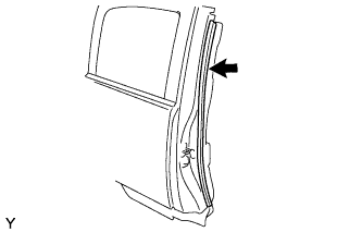
| 1. REMOVE ACCESS PANEL REAR WEATHERSTRIP |
|
Remove the access panel rear weatherstrip.
| 2. REMOVE LAP BELT OUTER ANCHOR COVER |
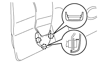 |
Disengage the 3 claws and remove the lap belt outer anchor cover.
| 3. REMOVE REAR DOOR INSIDE HANDLE SUB-ASSEMBLY |
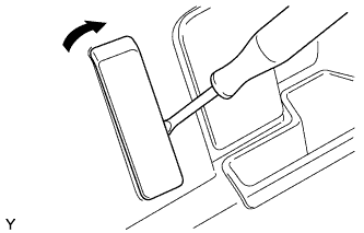 |
Insert a clip remover between the rear door inside handle sub-assembly and rear door trim board sub-assembly.
Turn the rear door inside handle sub-assembly with the clip remover inserted, as shown in the illustration.
Remove the rear door inside handle sub-assembly and snap ring.
| 4. REMOVE NO. 1 CUP HOLDER |
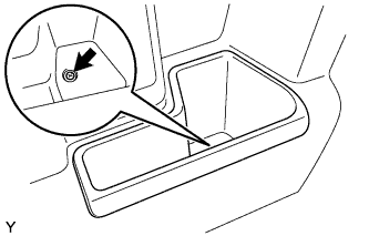 |
Remove the screw and No. 1 cup holder.
| 5. DISCONNECT FRONT SEAT OUTER BELT ASSEMBLY |
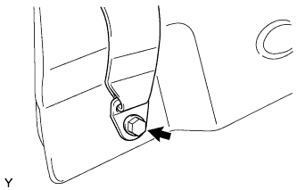 |
Remove the bolt and disconnect the front seat outer belt assembly.
| 6. REMOVE REAR DOOR TRIM BOARD SUB-ASSEMBLY |
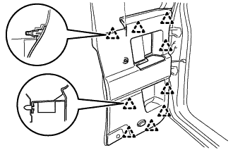 |
Disengage the 9 clips and remove the rear door trim board sub-assembly.
| 7. REMOVE REAR DOOR TRIM BRACKET |
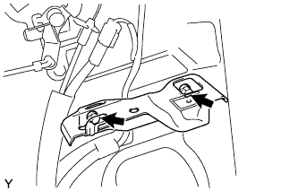 |
Remove the 2 screws and rear door trim bracket.
| 8. REMOVE CENTER PILLAR UPPER GARNISH |
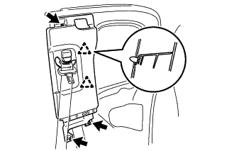 |
Remove the clip.
Remove the 2 screws.
Disengage the 2 clips.
Pass the floor anchor of the front seat outer belt assembly through the center pillar upper garnish and remove the center pillar upper garnish.
| 9. REMOVE FRONT SEAT OUTER BELT ASSEMBLY |
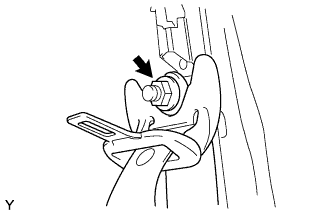 |
Remove the nut and the through anchor.
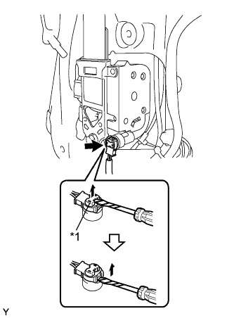 |
Using a screwdriver, release the locking button of the pretensioner connector.
| *1 | Locking Button |
Using a screwdriver, disconnect the pretensioner connector.
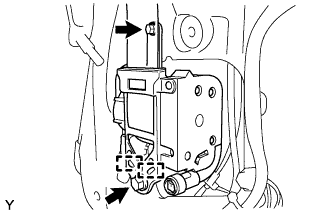 |
Remove the 2 bolts, the 2 hooks and the retractor.
| 10. REMOVE FRONT SHOULDER BELT ANCHOR ADJUSTER ASSEMBLY |
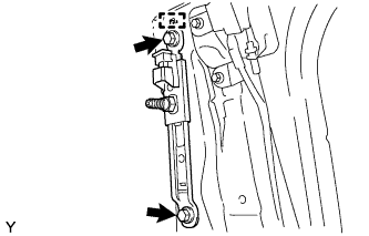 |
Remove the 2 bolts, the hook and the shoulder belt anchor adjuster.
| 11. REMOVE ACCESS PANEL INSIDE HANDLE SUB-ASSEMBLY |
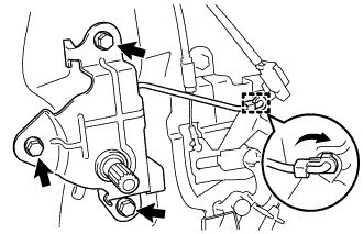 |
Disengage the snap and disconnect the rod.
Remove the 3 bolts and access panel inside handle sub-assembly.
| 12. REMOVE ACCESS PANEL UPPER LOCK ASSEMBLY |
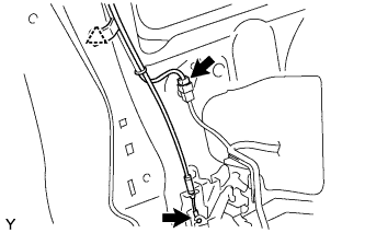 |
Disconnect the connector, harness clamp and the access panel lock control cable.
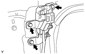 |
Remove the 3 bolts, then remove the access panel upper lock.
| 13. REMOVE ACCESS PANEL LOWER LOCK ASSEMBLY |
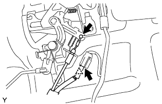 |
Disconnect the connector, connector clamp and access panel lock control cable.
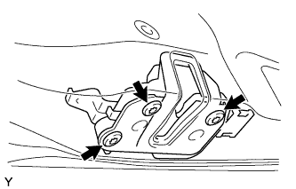 |
Using "Torx" socket wrench T30, remove the 3 screws.
Remove the access panel lower lock by sliding it upward.
| 14. REMOVE ACCESS PANEL LOCK REMOTE CONTROL ASSEMBLY |
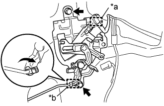 |
Disengage the clamp.
| *a | Clamp |
| *b | Snap |
Disengage the snap and disconnect the rod.
Remove the 2 bolts and access panel lock remote control assembly.
| 15. REMOVE ACCESS PANEL LOCK CANCEL LEVER ASSEMBLY |
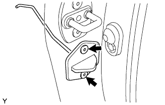 |
Using a T30 "TORX" socket wrench, remove the 2 screws and access panel lock cancel lever assembly.
| 16. REMOVE FRONT DOOR COURTESY SWITCH |
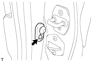 |
Remove the bolt and front door courtesy switch.
Disconnect the connector.
| 17. REMOVE ACCESS PANEL LOCK STRIKER PLATE ASSEMBLY |
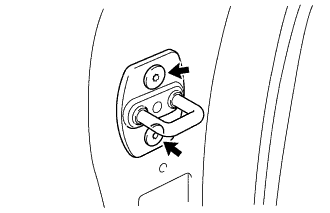 |
Using a T40 "TORX" socket wrench, remove the 2 screws and access panel lock striker plate assembly.
| 18. REMOVE REAR DOOR PANEL PROTECTOR |
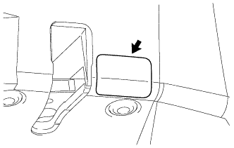 |
Remove the rear door panel protector.
| 19. REMOVE REAR DOOR OPENING TRIM |
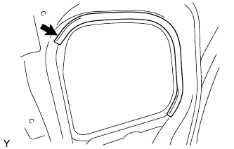 |
Remove the rear door opening trim.
| 20. REMOVE ACCESS PANEL CHECK ASSEMBLY |
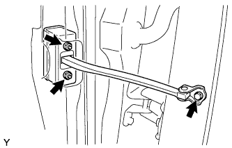 |
Remove the bolt, 2 nuts and access panel check assembly.
| 21. REMOVE ACCESS PANEL WEATHERSTRIP |
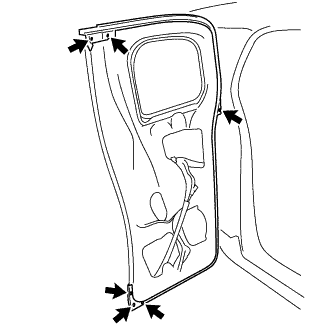 |
Using a clip remover, remove the 6 clips.
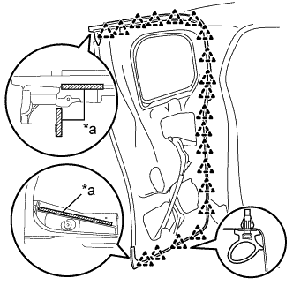 |
Using a clip remover, disengage the 20 clips.
| *a | Double-sided Tape |
Peel off the double-sided tape and remove the access panel weatherstrip.
| 22. REMOVE ACCESS PANEL LOWER LOCK STOP |
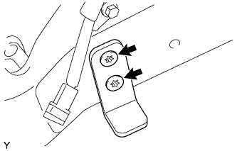 |
Using a T40 "TORX" socket wrench, remove the 2 screws and access panel lower lock stop.
| 23. REMOVE ACCESS DOOR OUTSIDE MOULDING SUB-ASSEMBLY |
| 24. REMOVE ACCESS DOOR GLASS OUTER WEATHERSTRIP |
| 25. REMOVE REAR DOOR GLASS |