CLUTCH MASTER CYLINDER > INSTALLATION |
| 1. INSTALL CLUTCH MASTER CYLINDER ASSEMBLY |
|
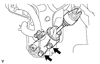
Install the clutch master cylinder with the 2 bolts.
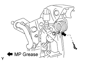 |
Apply MP grease to the pin.
Install the push rod clevis with the pin and clip.
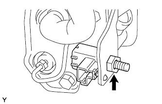 |
Install the clutch start switch with the nut.
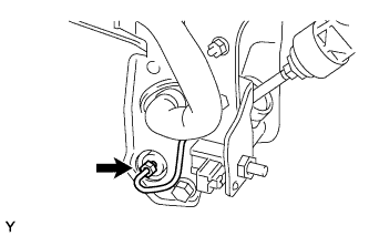 |
Using a union nut wrench, connect the clutch master cylinder to 2 way tube.
Connect the clutch reservoir tube.
| 2. INSTALL CLUTCH PEDAL WITH CLUTCH MASTER CYLINDER |
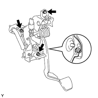 |
Install the clutch pedal with clutch master cylinder onto the vehicle with the 2 nuts and bolt.
Connect the clutch switch connector. (w/ Cruise Control)
Connect the clutch start switch connector.
| 3. INSTALL DRIVER SIDE JUNCTION BLOCK |
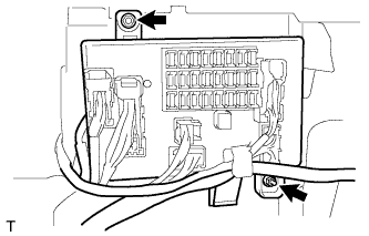 |
Install the main body ECU with the 2 nuts.
| 4. INSTALL INSTRUMENT PANEL LOWER LH |
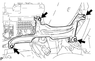 |
Install the lower instrument panel with the 4 <F> bolts.
| 5. INSTALL LOWER LH INSTRUMENT PANEL FINISH PANEL SUB-ASSEMBLY |
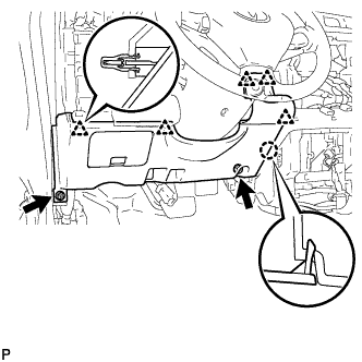 |
Engage the 5 clips and claw and install the lower instrument panel finish panel.
Connect the connector.
Install the 2 <F> bolts.
| 6. INSTALL NO. 1 INSTRUMENT PANEL REGISTER ASSEMBLY |
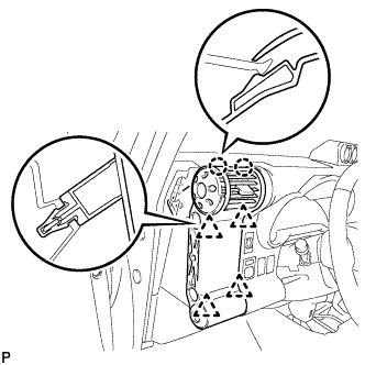 |
Engage the 4 clips and 2 claws and install the instrument panel register.
| 7. INSTALL COWL SIDE TRIM BOARD LH |
| 8. INSTALL FRONT DOOR SCUFF PLATE LH |
| 9. INSTALL FRONT FLOOR FOOTREST |
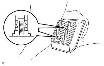 |
Engage the 2 studs and install the front floor footrest.
| 10. CONNECT CLUTCH MASTER CYLINDER TO FLEXIBLE HOSE TUBE |
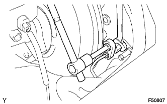 |
Using SST, connect the flexible hose tube.
| 11. CONNECT CLUTCH RESERVOIR TUBE |
| 12. BLEED CLUTCH PIPE LINE |
| 13. INSPECT AND ADJUST CLUTCH PEDAL SUB-ASSEMBLY |
Pull back the floor carpet.
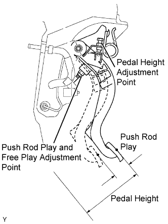 |
Check that the pedal height is correct.
Adjust the pedal height. (w/ Cruise Control)
Loosen the lock nut and turn the clutch switch until the height is correct. Tighten the lock nut.
Adjust the pedal height. (w/o Cruise Control)
Loosen the lock nut and turn the stopper bolt until the height is correct. Tighten the lock nut.
Check that the pedal free play and push rod play are correct.
Depress the pedal until the clutch resistance begins to be felt.
Gently depress the pedal until the resistance begins to increase a little.
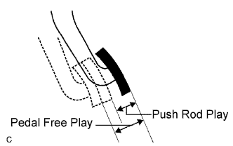 |
Adjust the pedal free play and push rod play.
Loosen the lock nut and turn the push rod until the free play and push rod play are correct.
Tighten the lock nut.
After adjusting the pedal free play, check the pedal height.
Connect the air duct and install the lower finish panel.
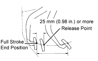 |
Check the clutch release point.
Pull the parking brake lever and chock the wheels.
Start the engine and allow it to idle.
Without depressing the clutch pedal, slowly move the shift lever into the reverse position until the gears engage.
Gradually depress the clutch pedal and measure the stroke distance from the point that the gear noise stops (release point) up to the full stroke end position.
| 14. CHECK FOR CLUTCH FLUID LEAKAGE |
| 15. CHECK FLUID LEVEL IN RESERVOIR |