
TIRE PRESSURE WARNING SYSTEM > TERMINALS OF ECU |
| CHECK TIRE PRESSURE WARNING ECU |
Disconnect the E74 tire pressure warning ECU connector.
Measure the voltage according to the value(s) in the table below.
| Terminal No. (Symbol) | Wiring Color | Terminal Description | Switch Condition | Specified Condition |
| E74-7 (IG) - E74-9 (GND) | B-R - W-B | IG power source | Ignition switch ON | 10 to 16 V |
Connect the E74 tire pressure warning ECU connector.
Measure the voltage and resistance according to the value(s) in the table below.
| Terminal No. (Symbol) | Wiring Color | Terminal Description | Condition | Specified Condition |
| E74-1 (CLSW) - E74-9 (GND) | B-L - W-B | Tire pressure warning reset switch | Ignition switch ON Tire pressure warning reset switch on | Below 1.5 V |
| Ignition switch ON Tire pressure warning reset switch off | 8 to 15 V | |||
| E74-2 (SPD) - E74-9 (GND) | V-R - W-B | Vehicle speed signal | Vehicle is running | Pulse generation (see waveform 1) |
| E74-3 (TC) - E74-9 (GND) | P-L - W-B | TC terminal | Terminal TC not connected | 8 to 15 V |
| Terminal TC connected | Below 1.2 V | |||
| E74-4 (TACH) - E74-9 (GND) | B-W - W-B | Engine speed signal | Engine is running | Pulse generation (see waveform 2) |
| E74-5 (IND) - E74-9 (GND) | P-B - W-B | Tire pressure warning light output signal | After ignition switch is turned ON, when tire pressure warning light illuminates for 3 seconds | 1.6 to 2.4 V |
| Ignition switch ON Tire pressure warning light off | 4 V or higher | |||
| E74-6 (RF5V) - E74-9 (GND) | L - W-B | Tire pressure warning antenna and receiver power source | Ignition switch ON | 4.5 to 5.5 V |
| E74-7 (IG) - E74-9 (GND) | B-R- W-B | IG power source | Ignition switch ON | 11 to 14 V |
| E74-9 (GND) - Body ground | W-B - Body ground | Ground | Always | Below 1 Ω |
| E74-10 (SIL) - E74-9 (GND) | R-Y - W-B | Diagnosis tester communication line | Ignition switch ON, when communication is not performed with a tester | 8 to 15 V |
| E74-11 (GND2) - E74-9 (GND) | LG-B - W-B | Tire pressure warning antenna and receiver ground | Always | Below 1 Ω |
| E74-12 (RDA) - E74-9 (GND) | GR - W-B | Tire pressure warning antenna and receiver signal | Ignition switch ON Disconnect the L24 tire pressure warning antenna and receiver connector | 11 to 14 V |
| Ignition switch ON Connect the L24 tire pressure warning antenna and receiver connector | Below 2 V |
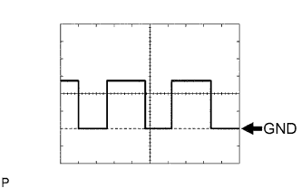 |
Using an oscilloscope, check the waveform 1.
| Item | Contents |
| Terminal No. (Symbols) | E74-2 (SPD) - E74-9 (GND) |
| Tool Setting | 5 V/DIV., 200 ms/DIV. |
| Vehicle Condition | While driving at approximately 20 km/h (12 mph). |
|
Using an oscilloscope, check the waveform 2.
| Item | Contents |
| Terminal No. (Symbols) | E74-4 (TACH) - E74-9 (GND) |
| Tool Setting | 5 V/DIV., 10 ms/DIV. |
| Vehicle Condition | Idling |