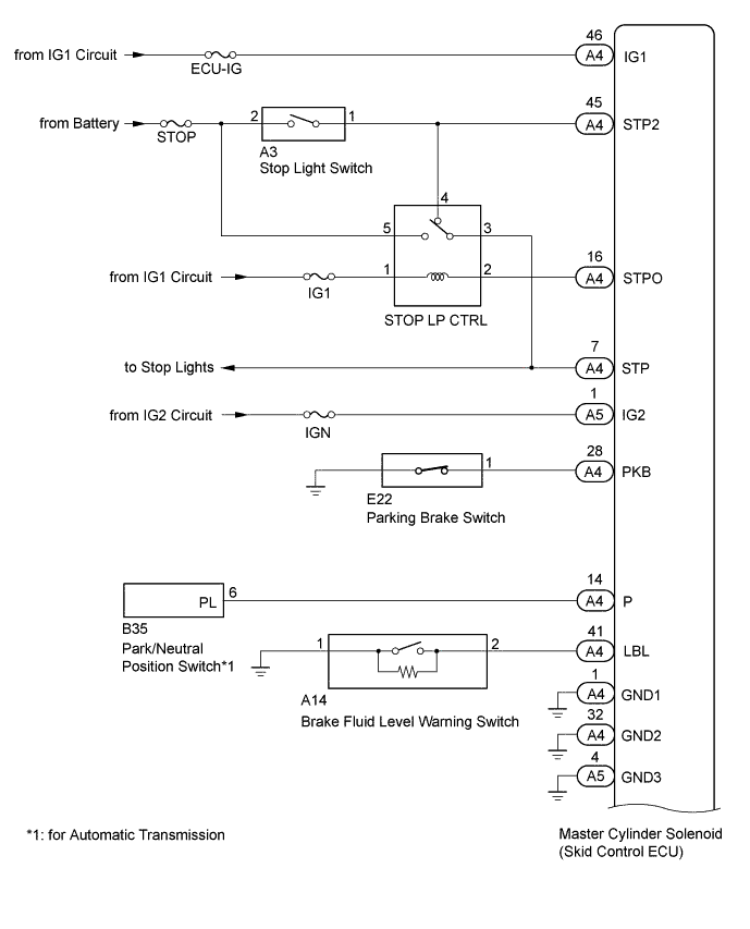
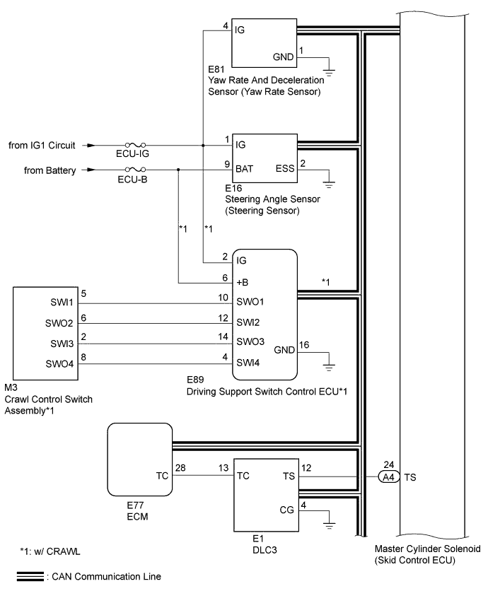
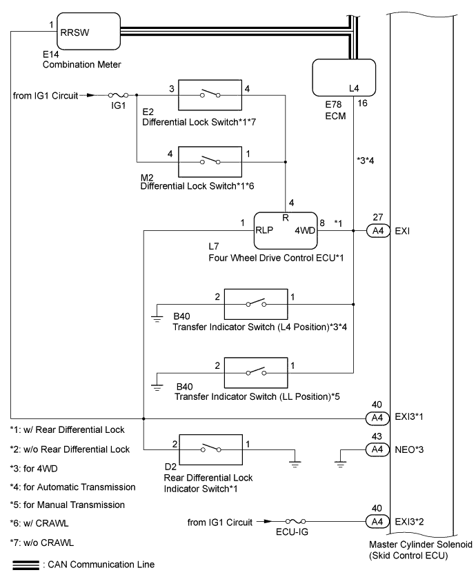
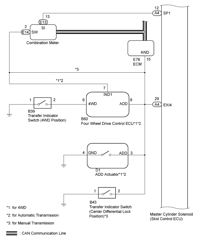
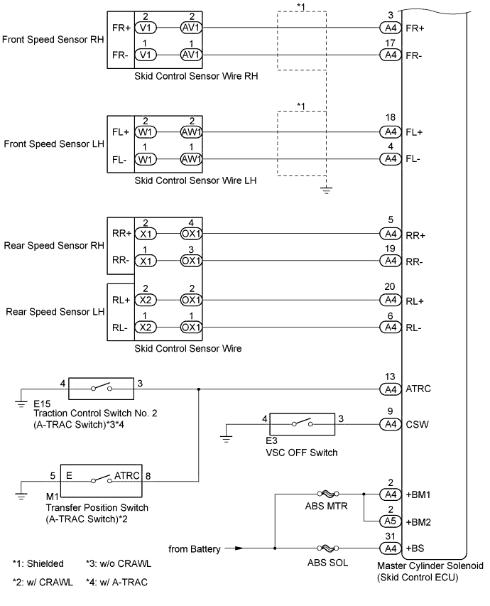
Transmitting ECU (Transmitter)
| Receiving ECU
| Signals
| Communication Method
|
ECM
| Skid control ECU
| - Engine speed signal
- Accelerator pedal position signal
- Intake air temperature signal
- Shift position signal
- TC terminal status
| CAN communication line
|
Skid control ECU
| ECM
| - Yaw rate and deceleration signal
- VSC data signal
- Wheel speed signal
| CAN communication line
|
Skid control ECU
| Combination meter
| - Warning/indicator light signal
- Vehicle speed signal
| CAN communication line
|
Yaw rate and deceleration sensor
| Skid control ECU
| Yaw rate and deceleration signal
| CAN communication line
|
Steering angle sensor
| Skid control ECU
| Steering angle signal
| CAN communication line
|
Driving Support Switch Control ECU*1
| Skid control ECU
| - Crawl control on SW signal
- Crawl control mode SW signal
| CAN communication line
|