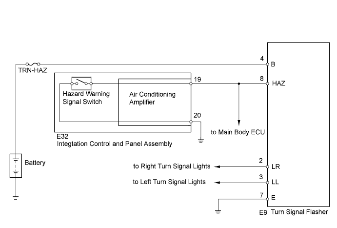
LIGHTING SYSTEM > Hazard Warning Switch Circuit |
| 1.PERFORM ACTIVE TEST USING TECHSTREAM (HAZARD) |
Connect the Techstream to the DLC3.
Turn the ignition switch to ON.
Turn the tester on.
Enter the following menus: Body Electrical / Body / Active Test / Hazard
Check the hazard warning signal light while operating the hazard using the tester.
| Tester Display | Test Part | Control Range | Normal Condition |
| Hazard | Turn signal flasher | ON/OFF | - |
|
| ||||
| NG | |
 |
| 2.INSPECT FUSE (TRN-HAZ) |
Remove the TRN-HAZ fuse from the No. 2 engine room relay block.
Measure the resistance according value(s) in the table below.
| Tester Connection | Condition | Specified Condition |
| TRN-HAZ fuse | Always | Below 1 Ω |
Reinstall the TRN-HAZ fuse.
|
| ||||
| OK | |
|
| 3.CHECK HARNESS AND CONNECTOR (FUSE - TURN SIGNAL FLASHER RELAY - BODY GROUND) |
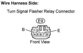 |
Disconnect the E9 turn signal flasher relay connector.
Measure the voltage according value(s) in the table below.
| Tester Connection | Condition | Specified Condition |
| E9-4 (B) - Body ground | Always | 11 to 14 V |
Measure the resistance according value(s) in the table below.
| Tester Connection | Condition | Specified Condition |
| E9-7 (E) - Body ground | Always | Below 1 Ω |
Reconnect the turn signal flasher relay connector.
|
| ||||
| OK | ||
 | ||
| ||
| 4.INSPECT INTEGRATION CONTROL AND PANEL ASSEMBLY (HAZARD WARNING SWITCH) |
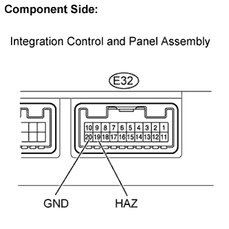 |
Disconnect the E32 integration control and panel assembly connector.
Measure the resistance according value(s) in the table below.
| Tester Connection | Condition | Specified Condition |
| 19 (HAZ) - 20 (GND) | Hazard warning switch OFF | 10 kΩ or higher |
| 19 (HAZ) - 20 (GND) | Hazard warning switch ON | Below 3 Ω |
Reconnect the integration control and panel assembly connector.
|
| ||||
| OK | |
|
| 5.CHECK HARNESS AND CONNECTOR (INTEGRATION CONTROL AND PANEL - MAIN BODY ECU, BODY GROUND) |
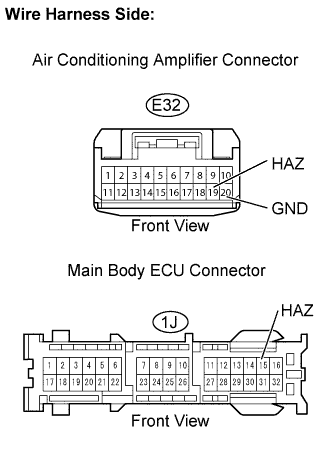 |
Disconnect the E32 integration control and panel assembly connector.
Disconnect the 1J main body ECU connector.
Measure the resistance according value(s) in the table below.
| Tester Connection | Condition | Specified Condition |
| E32-19 (HAZ) - 1J-15 (HAZ) | Always | Below 1 Ω |
| E32-19 (HAZ) or 1J-15 (HAZ) - Body ground | Always | 10 kΩ or higher |
| E32-20 (GND) - Body ground | Always | Below 1 Ω |
Reconnect the integration control and panel assembly connector.
Reconnect the main body ECU connector.
|
| ||||
| OK | ||
| ||
| ||

