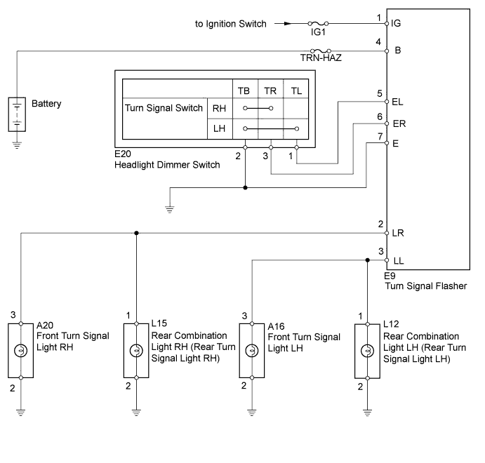
LIGHTING SYSTEM > Turn Signal Light Circuit |
| 1.CHECK OPERATION (TURN SIGNAL LIGHT) |
When the turn signal light switch is operated, check that the appropriate turn signal light flashes.
| Condition | Proceed to |
| No lights flash | A |
| Front turn signal light (LH or RH) does not flash | B |
| Rear turn signal light (LH or RH) does not flash | C |
|
| ||||
|
| ||||
| A | |
 |
| 2.INSPECT FUSE (IG1, TRN-HAZ) |
Remove the IG1 fuse from the main body ECU.
Remove the TRN-HAZ fuse from the No. 2 engine room relay block.
Measure the resistance according value(s) in the table below.
| Tester Connection | Condition | Specified Condition |
| IG1 fuse | Always | Below 1 Ω |
| TRN-HAZ fuse | Always | Below 1 Ω |
Reinstall the IG1 and TRN-HAZ fuses.
|
| ||||
| OK | |
|
| 3.INSPECT TURN SIGNAL FLASHER RELAY |
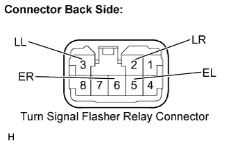 |
Measure the voltage according value(s) in the table below.
| Tester Connection | Condition | Specified Condition |
| 2 (LR) - Body ground | Turn signal switch (right turn) OFF → ON | 0 V → 11 to 14 V (60 to 120 times per minute) |
| 3 (LL) - Body ground | Turn signal switch (left turn) OFF → ON | 0 V → 11 to 14 V (60 to 120 times per minute) |
| 5 (EL) - Body ground | Turn signal switch (left turn) OFF → ON | 11 to 14 V → 0 V |
| 6 (ER) - Body ground | Turn signal switch (right turn) OFF → ON | 11 to 14 V → 0 V |
|
| ||||
| OK | |
|
| 4.CHECK HARNESS AND CONNECTOR (FUSE - TURN SIGNAL FLASHER RELAY) |
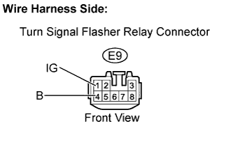 |
Disconnect the E9 turn signal flasher relay connector.
Measure the voltage according value(s) in the table below.
| Tester Connection | Condition | Specified Condition |
| E9-1(IG) - Body ground | Ignition switch ON | 11 to 14 V |
| E9-4 (B) - Body ground | Always | 11 to 14 V |
Reconnect the turn signal flasher relay connector.
|
| ||||
| OK | |
|
| 5.INSPECT HEADLIGHT DIMMER SWITCH |
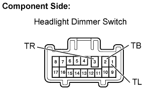 |
Remove the headlight dimmer switch.
Inspect the turn signal light switch.
Measure the resistance according value(s) in the table below.
| Tester Connection | Condition | Specified Condition |
| 2 (TB) - 3 (TR) | Right | Below 1 Ω |
| 2 (TB) - 3 (TR) | Neutral | 10 kΩ or higher |
| 2 (TB) - 1 (TL) | Left | Below 1 Ω |
| 2 (TB) - 1 (TL) | Neutral | 10 kΩ or higher |
Reinstall the headlight dimmer switch.
|
| ||||
| OK | |
|
| 6.CHECK HARNESS AND CONNECTOR (TURN SIGNAL FLASHER RELAY - HEADLIGHT DIMMER SWITCH) |
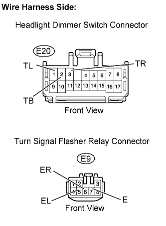 |
Disconnect the E20 headlight dimmer switch connector.
Disconnect the E9 turn signal flasher relay connector.
Measure the resistance according value(s) in the table below.
| Tester Connection | Condition | Specified Condition |
| E20-2 (TB) - E9 -7 (E) | Always | Below 1 Ω |
| E20-2 (TB) or E9 -7 (E) - Body ground | Always | 10 kΩ or higher |
| E20-1 (TL) - E9-5 (EL) | Always | Below 1 Ω |
| E20-1 (TL) or E9-5 (EL) - Body ground | Always | 10 kΩ or higher |
| E20-3 (TR) - E9-6 (ER) | Always | Below 1 Ω |
| E20-3 (TR) or E9-6 (ER) - Body ground | Always | 10 kΩ or higher |
Reconnect the headlight dimmer switch connector.
Reconnect the turn signal flasher relay connector.
|
| ||||
| OK | |
|
| 7.CHECK HARNESS AND CONNECTOR (TURN SIGNAL FLASHER RELAY - BODY GROUND) |
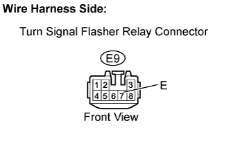 |
Disconnect the E9 turn signal flasher relay connector.
Measure the resistance according value(s) in the table below.
| Tester Connection | Condition | Specified Condition |
| E9-7 (E) - Body ground | Always | Below 1 Ω |
Reconnect the turn signal flasher relay connector.
|
| ||||
| OK | ||
 | ||
| ||
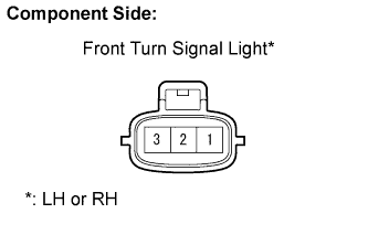
| 8.INSPECT BULB (FRONT TURN SIGNAL LIGHT BULB) |
 |
Remove the front turn signal light.
Apply battery voltage to the terminals and check that the front turn signal light illuminates.
| Measurement Condition | Specified Condition |
| Positive battery - Terminal 3 Negative battery - Terminal 2 | Front turn signal light illuminates |
Reinstall the front turn signal light.
|
| ||||
| OK | |
|
| 9.CHECK HARNESS AND CONNECTOR (TURN SIGNAL FLASHER RELAY - FRONT TURN SIGNAL LIGHT) |
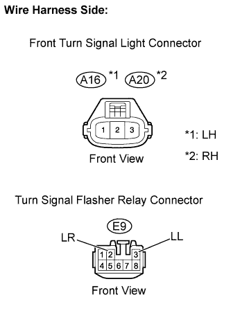 |
Disconnect the E9 turn signal flasher relay connector.
Disconnect the A16 and A20 front turn signal light connectors.
Measure the resistance according value(s) in the table below.
| Tester Connection | Condition | Specified Condition |
| E9-2 (LR) - A20-3 | Always | Below 1 Ω |
| E9-2 (LR) or A20-3 - Body ground | Always | 10 kΩ or higher |
| E9-3 (LL) - A16-3 | Always | Below 1 Ω |
| E9-3 (LL) or A16-3 - Body ground | Always | 10 kΩ or higher |
Reconnect the turn signal flasher relay connector.
Reconnect the front turn signal light connectors.
|
| ||||
| OK | ||
| ||
| ||
| 10.INSPECT BULB (REAR TURN SIGNAL LIGHT BULB) |
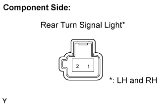 |
Remove the rear turn signal light.
Apply battery voltage to the terminals and check that the rear turn signal light illuminates.
| Measurement Condition | Specified Condition |
| Positive battery - Terminal 1 Negative battery - Terminal 2 | Rear turn signal light illuminates |
Reinstall the rear turn signal light.
|
| ||||
| OK | |
|
| 11.CHECK HARNESS AND CONNECTOR (TURN SIGNAL FLASHER RELAY - REAR TURN SIGNAL LIGHT) |
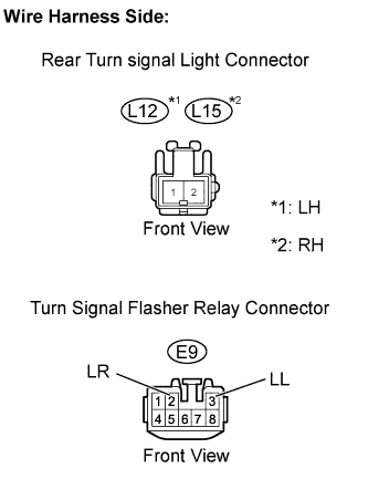 |
Disconnect the E9 turn signal flasher relay connector.
Disconnect the L12 and L15 rear turn signal light connectors.
Measure the resistance according value(s) in the table below.
| Tester Connection | Condition | Specified Condition |
| E9-2 (LR) - L15-1 | Always | Below 1 Ω |
| E9-2 (LR) or L15-1 - Body ground | Always | 10 kΩ or higher |
| E9-3 (LL) - L12-1 | Always | Below 1 Ω |
| E9-3 (LL) or L12-1 - Body ground | Always | 10 kΩ or higher |
Reconnect the turn signal flasher relay connector.
Reconnect the rear turn signal light connectors.
|
| ||||
| OK | ||
| ||
| ||

