Home › ENGINE › 1GR-FE CHARGING › GENERATOR

GENERATOR > INSTALLATION

for Preparation Click here


1. INSTALL GENERATOR ASSEMBLY
  1. Install the generator bracket to the generator with the bolt.

    Torque:
    20 N*m{ 204 kgf*cm , 15 ft.*lbf }

  1. Install the generator with the 2 bolts.

    Torque:
    43 N*m{ 438 kgf*cm , 32 ft.*lbf }

  1. Install the generator bracket with the bolt.

    Torque:
    20 N*m{ 204 kgf*cm , 15 ft.*lbf }

  1. Attach the wire harness clamp.

  1. Install the wire harness with the 2 bolts.

    Torque:
    8.0 N*m{ 82 kgf*cm , 71 in.*lbf }

  1. Connect the generator connector to the generator.

  1. Install the generator wire with the nut.

    Torque:
    9.8 N*m{ 100 kgf*cm , 87 in.*lbf }

  1. Close the terminal cap.


2. INSTALL FRONT FENDER APRON SEAL LH
  1. Install the front fender apron seal LH to the front fender apron sub-assembly LH with the 5 clips.


3. INSTALL NO. 2 EXHAUST MANIFOLD HEAT INSULATOR
  1. Install the No. 2 exhaust manifold heat insulator to the exhaust manifold sub-assembly LH with the 3 bolts.

    Torque:
    13 N*m{ 133 kgf*cm , 10 ft.*lbf }


4. INSTALL WIRING HARNESS CLAMP BRACKET
  1. Install the wiring harness clamp bracket with the bolt.

    Torque:
    8.0 N*m{ 82 kgf*cm , 71 in.*lbf }

  1. Connect the clamp.


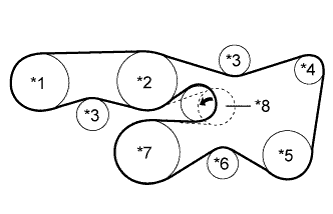
5. INSTALL FAN AND GENERATOR V BELT


    A225650E01
  1. Set the fan and generator V belt onto every part.
    Text in Illustration 
    *1
    Vane Pump Assembly
    *2
    Engine Water Pump Assembly
    *3
    No. 2 Idler Pulley Sub-Assembly
    *4
    Generator Assembly
    *5
    Cooler Compressor Assembly
    *6
    No. 1 Idler Pulley Sub-Assembly
    *7
    Crankshaft Pulley
    *8
    V-ribbed Belt Tensioner Assembly

  1. While turning the V-ribbed belt tensioner assembly counterclockwise, remove the pin.

    NOTICE:
    Make sure that the fan and generator V belt is properly set to each pulley.

  1. Check that the belt fits properly in the ribbed grooves.

    HINT:
    Make sure to check by hand that the belt has not slipped out of the grooves on the bottom of the pulley.


6. INSTALL V-BANK COVER
  1. Engage the 2 hooks and install the V-bank cover to the No. 1 V-bank cover bracket.

  1. Align the 2 V-bank cover grommets with the 2 pins and press down on the V-bank cover to engage the pins.


7. INSTALL BATTERY TRAY


8. INSTALL BATTERY


9. INSTALL BATTERY HOLD DOWN CLAMP
  1. Install the battery hold down clamp and tighten the 2 nuts.

    Torque:
    6.0 N*m{ 61 kgf*cm , 53 in.*lbf }


10. CONNECT CABLE TO POSITIVE BATTERY TERMINAL

Torque:
3.9 N*m{ 40 kgf*cm , 35 in.*lbf }


11. CONNECT CABLE TO NEGATIVE BATTERY TERMINAL

Torque:
3.9 N*m{ 40 kgf*cm , 35 in.*lbf }

NOTICE:
When disconnecting the cable, some systems need to be initialized after the cable is reconnected (Click here).