 |
Pull the rear seatback lock release button and tilt the rear seatback forward.
ROOF SPEAKER > REMOVAL |
| 1. REMOVE REAR SEATBACK BOARD CARPET ASSEMBLY RH |
|
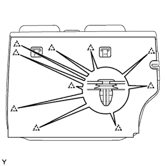
Pull the rear seatback lock release button and tilt the rear seatback forward.
Disengage the 10 clips and remove the rear seatback board carpet.
| 2. REMOVE REAR SEATBACK ASSEMBLY RH |
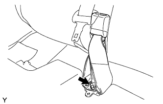 |
Pull up the rear seatback.
Remove the bolt and the anchor plate of the rear center seat outer belt.
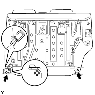 |
Remove the rear seat inner belt from the rear seatback holder.
Pull the rear seatback lock release button and tilt the rear seatback forward.
Remove the 2 bolts.
Disengage the hook and remove the rear seatback.
| 3. REMOVE REAR SEATBACK BOARD CARPET ASSEMBLY LH |
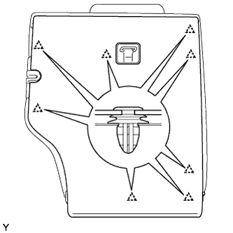 |
Pull the rear seatback lock release button and tilt the rear seatback forward.
Disengage the 8 clips and remove the rear seatback board carpet.
| 4. REMOVE REAR SEATBACK ASSEMBLY LH |
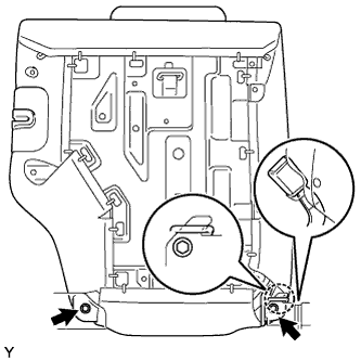 |
Remove the rear center seat inner belt from the rear seatback holder.
Remove the 2 bolts.
Disengage the hook and remove the rear seatback.
| 5. REMOVE REAR FLOOR BOARD |
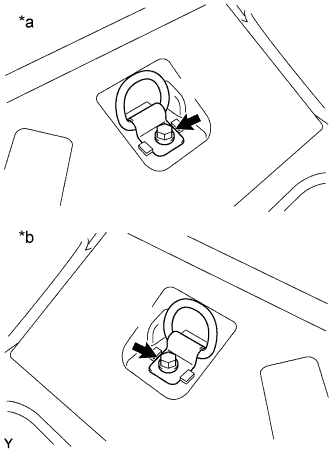 |
Remove the bolt and the luggage hold belt striker.
| *a | for RH Side |
| *b | for LH Side |
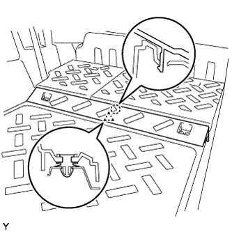 |
Disengage the clip and the claw and remove the rear floor board.
| 6. REMOVE REAR FLOOR MAT SUPPORT PLATE |
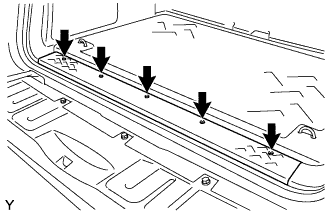 |
Remove the 5 screws.
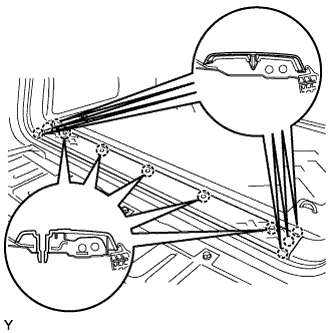 |
Disengage the 11 claws and remove the rear floor mat support plate.
| 7. REMOVE LUGGAGE HOLD BELT STRIKER ASSEMBLY |
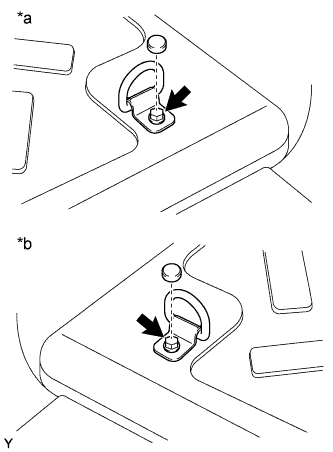 |
| *a | for RH Side |
| *b | for LH Side |
Remove the cap.
Remove the bolt and the luggage hold belt striker.
| 8. REMOVE REAR FLOOR MAT ASSEMBLY |
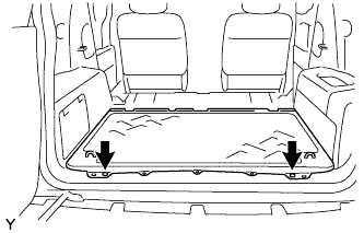 |
Using a clip remover, remove the 2 clips and the rear floor mat.
| 9. REMOVE FRONT DOOR SCUFF PLATE RH |
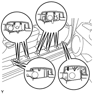 |
Disengage the 14 claws and remove the front door scuff plate.
| 10. REMOVE FRONT DOOR SCUFF PLATE LH |
| 11. REMOVE ACCESS DOOR SCUFF PLATE RH |
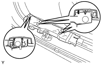 |
Disengage the 6 claws and remove the access door scuff plate.
| 12. REMOVE ACCESS DOOR SCUFF PLATE LH |
| 13. REMOVE FRONT FLOOR FOOTREST |
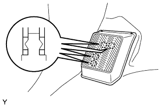 |
Disengage the 4 claws and remove the front floor footrest.
| 14. REMOVE FOOTREST CLIP |
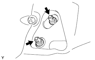 |
Remove the 2 footrest clips.
| 15. REMOVE COWL SIDE TRIM BOARD RH |
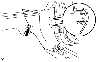 |
Remove the clip.
Disengage the 2 claws and remove the cowl side trim board.
| 16. REMOVE COWL SIDE TRIM BOARD LH |
| 17. REMOVE ROOF SIDE INNER GARNISH COVER RH |
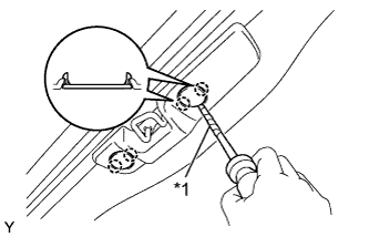 |
| *1 | Protective Tape |
Using a screwdriver with its tip wrapped in protective tape, disengage the 2 claws and remove the roof side inner garnish cover.
| 18. REMOVE ROOF SIDE INNER GARNISH COVER LH |
| 19. REMOVE ROOF SIDE RAIL GARNISH RH |
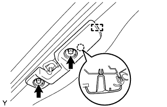 |
Remove the 2 bolts.
Disengage the claw and the guide remove the roof side rail garnish.
| 20. REMOVE ROOF SIDE RAIL GARNISH LH |
| 21. REMOVE FRONT DOOR OPENING TRIM WEATHERSTRIP RH |
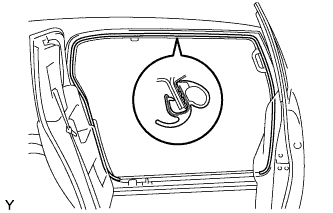 |
Remove the front door opening trim weatherstrip.
| 22. REMOVE FRONT DOOR OPENING TRIM WEATHERSTRIP LH |
| 23. REMOVE ASSIST GRIP PLUG |
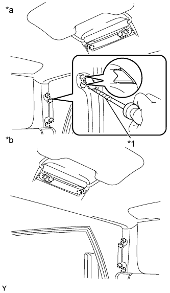 |
| *1 | Protective Tape |
| *a | for RH Side |
| *b | for LH Side |
Using a screwdriver with its tip wrapped in protective tape, disengage the 2 claws and remove the assist grip plug.
| 24. REMOVE ASSIST GRIP ASSEMBLY |
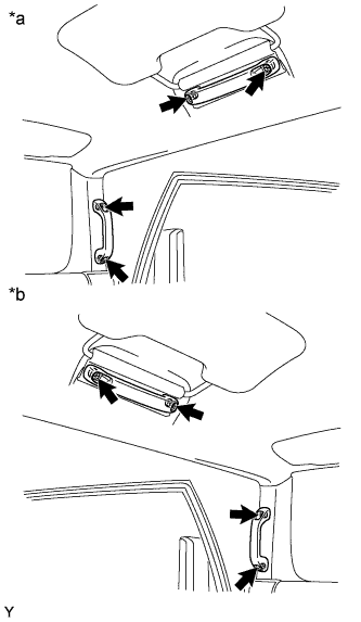 |
| *a | for RH Side |
| *b | for LH Side |
Remove the 2 screws and the assist grip.
| 25. REMOVE VISOR SUB-ASSEMBLY RH |
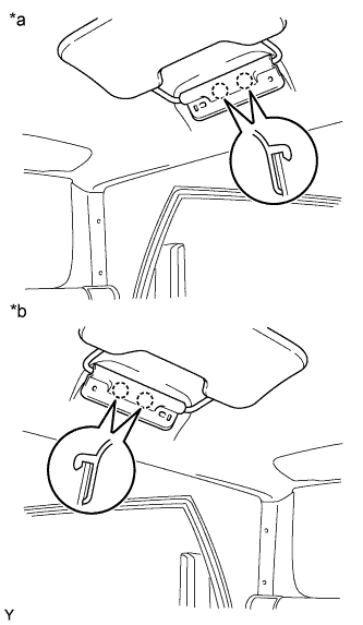 |
Disengage the 2 claws and remove the visor sub-assembly.
| *a | for RH Side |
| *b | for LH Side |
| 26. REMOVE VISOR SUB-ASSEMBLY LH |
| 27. REMOVE FRONT PILLAR GARNISH RH |
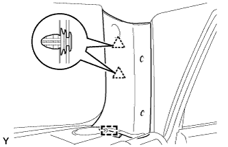 |
Disengage the 2 clips and the guide and remove the front pillar garnish.
| 28. REMOVE FRONT PILLAR GARNISH LH |
| 29. REMOVE PACKAGE HOLDER NET HOOK |
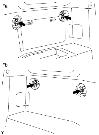 |
| *a | for RH Side without Woofer |
| *b | for LH Side |
Remove the screw and the package holder net hook.
| 30. REMOVE QUARTER TRIM POCKET TRAY |
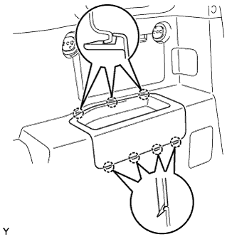 |
Disengage the 7 claws and remove the quarter trim pocket tray.
| 31. REMOVE SIDE TRIM COVER |
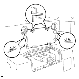 |
Disengage the 6 claws and the 2 guides remove the side trim cover.
| 32. REMOVE QUARTER TRIM POCKET |
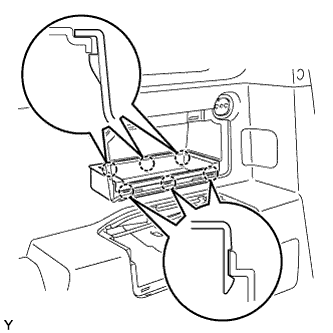 |
Disengage the 6 claws and remove the quarter trim pocket.
| 33. REMOVE LAP BELT OUTER ANCHOR COVER |
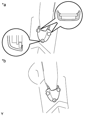 |
| *a | for RH Side |
| *b | for LH Side |
Disengage the 3 claws and remove the lap belt outer anchor cover.
| 34. REMOVE REAR SEAT OUTER BELT ASSEMBLY RH |
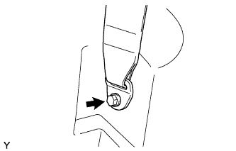 |
Remove the bolt and the anchor plate.
| 35. REMOVE REAR SEAT OUTER BELT ASSEMBLY LH |
| 36. REMOVE REAR DECK TRIM COVER (w/ Power Outlet Socket) |
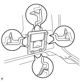 |
Disengage the 8 claws and remove the rear deck trim cover.
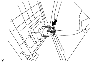 |
Disconnect the power outlet connector.
| 37. REMOVE DECK TRIM SIDE PANEL ASSEMBLY RH |
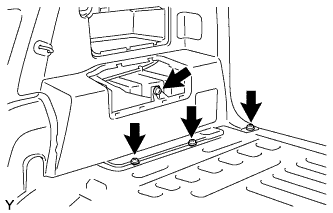 |
Remove the 3 screws and bolt.
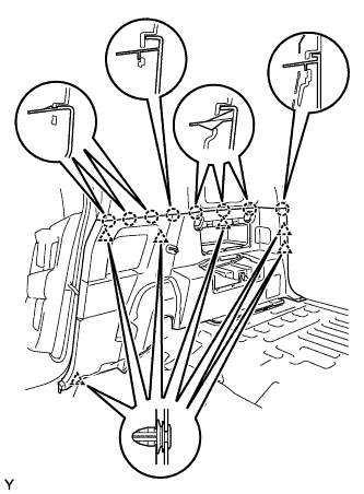 |
Disengage the 6 clips and the 8 claws and remove the deck trim side panel.
| 38. REMOVE DECK TRIM SIDE PANEL ASSEMBLY LH |
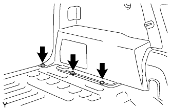 |
Remove the 3 screws.
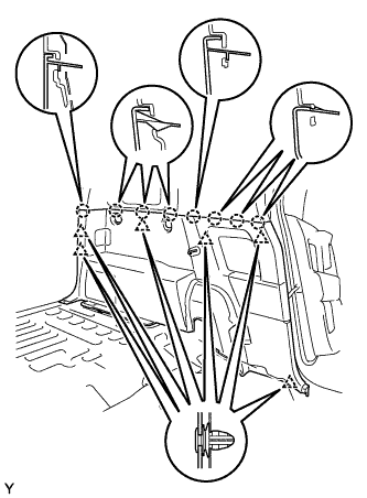 |
Disengage the 6 clips and the 8 claws and remove the deck trim side panel.
| 39. REMOVE ROOF SIDE INNER GARNISH RH |
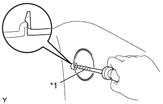 |
Using a screwdriver with its tip wrapped in protective tape, disengage the claw and open the cover.
| *1 | Protective Tape |
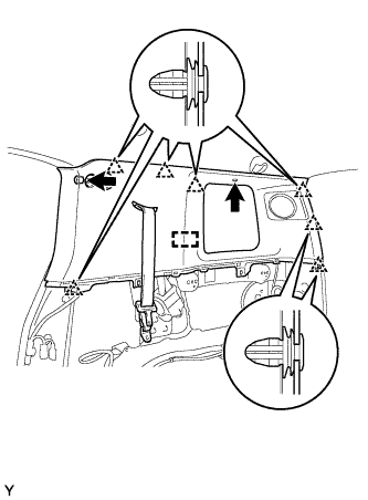 |
Remove the bolt and the clip.
Disengage the 7 clips and the guide and remove the roof side inner garnish.
Pass the rear seat outer belt through the slit in the roof side inner garnish.
| 40. REMOVE ROOF SIDE INNER GARNISH LH |
| 41. REMOVE ROOF HEADLINING HOLE PLUG |
 |
| *1 | Protective Tape |
| *a | for RH Side |
| *b | for LH Side |
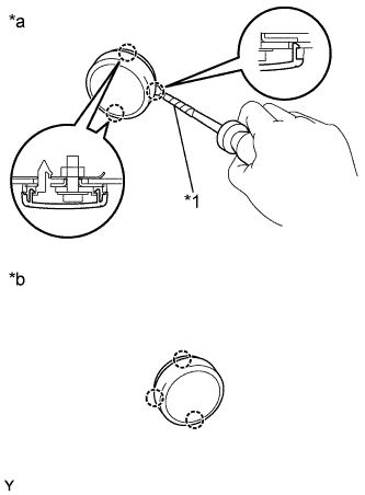
Using a screwdriver with its tip wrapped in protective tape, disengage the 3 claws and open the cover.
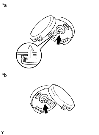 |
Remove the bolt.
| *a | for RH Side |
| *b | for LH Side |
Disengage the claw and remove the roof headlining hole plug.
| 42. REMOVE COAT HOOK |
 |
| *1 | Protective Tape |
| *a | for RH Side |
| *b | for LH Side |
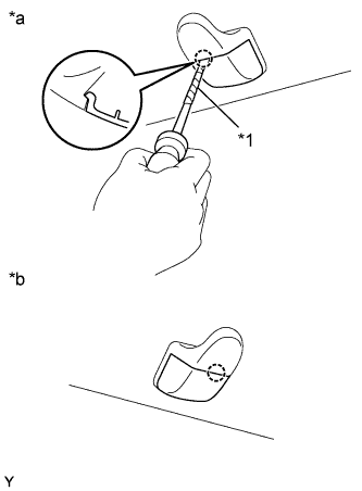
Using a screwdriver with its tip wrapped in protective tape, disengage the claw and open the cover.
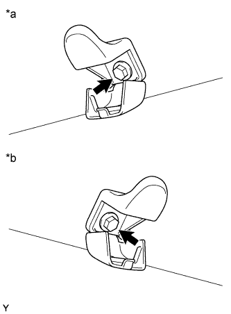 |
Remove the bolt and the coat hook.
| *a | for RH Side |
| *b | for LH Side |
| 43. REMOVE VISOR ASSEMBLY RH |
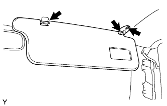 |
Remove the visor support shaft from the visor holder.
Remove the 2 screws and the visor.
| 44. REMOVE VISOR ASSEMBLY LH |
| 45. REMOVE VISOR HOLDER |
 |
| *a | for RH Side |
| *b | for LH Side |
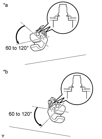
Disengage the 2 claws by turning the visor counterclockwise between 60 to 120° and remove the visor holder.
| 46. REMOVE INNER REAR VIEW MIRROR ASSEMBLY |
| 47. REMOVE ROOM LIGHT ASSEMBLY |
 |
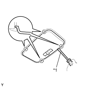 |
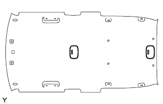
Using a screwdriver with its tip wrapped in protective tape, disengage the 4 claws and remove the room light lens.
| *1 | Protective Tape |
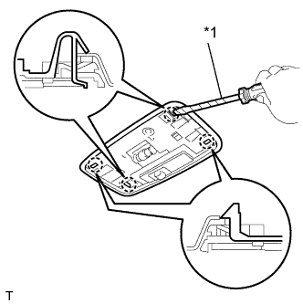 |
Using a screwdriver with its tip wrapped in protective tape, disengage the 4 claws and remove the room light.
| *1 | Protective Tape |
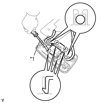 |
for Front Side:
| *1 | Protective Tape |
Remove the 2 wire harnesses from the 2 claws of the room light.
Using a screwdriver with its tip wrapped in protective tape, disengage the 4 claws and remove the room light switch base.
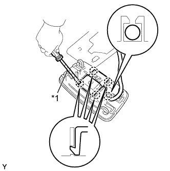 |
for Rear Side:
| *1 | Protective Tape |
Remove the wire harness from the claw of the room light.
Using a screwdriver with its tip wrapped in protective tape, disengage the 4 claws and remove the room light switch base.
| 48. REMOVE PERSONAL LIGHT ASSEMBLY (w/ CRAWL) |
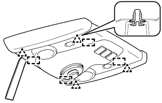 |
Using a moulding remover, disengage the 4 clips and 4 guides.
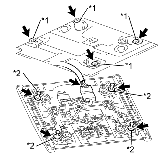 |
Disconnect the connector and remove the personal light assembly.
| *1 | Grommet |
| *2 | Pin |
Remove the 4 pins.
Remove the 4 grommets from the body side.
| 49. SEPARATE ROOF HEADLINING |
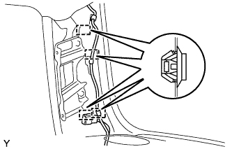 |
Using a clip remover, disengage the 4 clamps.
w/ Satellite Radio:
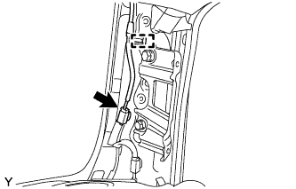 |
Using a clip remover, disengage the clamp and disconnect the antenna cord connector.
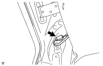 |
Disconnect the antenna cord connector.
Using a clip remover, remove the 4 clips.
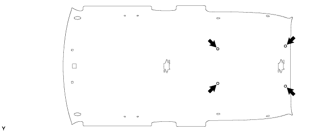
| 50. REMOVE ROOF SPEAKER ASSEMBLY |
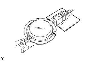 |
Remove the hole cover.
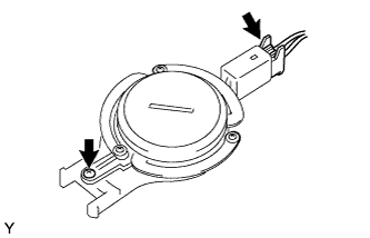 |
Disconnect the speaker connector.
Loosen the screw.
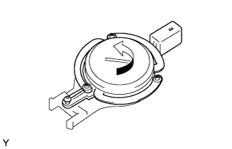 |
Remove the roof speaker by turning it in the direction of the arrow shown in the illustration.