 |
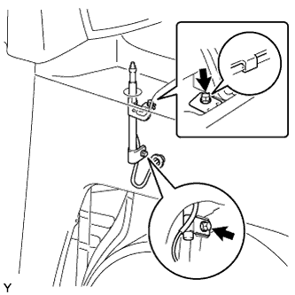
Hook the body side bracket onto the hook of the radio antenna holder and provisionally install the radio antenna holder.
RADIO ANTENNA HOLDER > INSTALLATION |
| 1. INSTALL RADIO ANTENNA HOLDER ASSEMBLY |
|
Hook the body side bracket onto the hook of the radio antenna holder and provisionally install the radio antenna holder.
Insert the feeder line through the body hole and install the grommet.
Tighten bolt A and then bolt B.
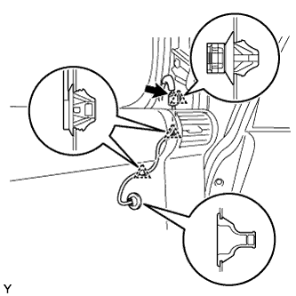 |
Install the 2 clamps and the connector.
Connect the connector.
| 2. INSTALL FENDER SPLASH REAR SHIELD SUB-ASSEMBLY |
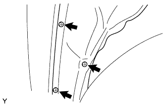 |
Install the fender splash rear shield with the 3 clips.
| 3. INSTALL FRONT FENDER SIDE UPPER PANEL |
Install the 4 new clips on the front fender side panel upper RH.
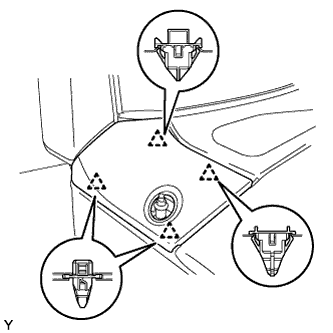 |
Engage the 4 clips and install the front fender side panel upper RH.
| 4. INSTALL ANTENNA ORNAMENT |
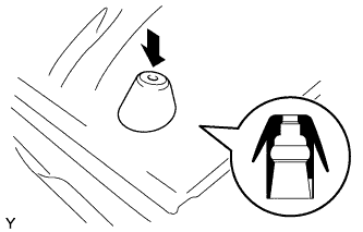 |
Press in the antenna ornament in the direction shown in the illustration.
| 5. INSTALL RADIO ANTENNA POLE SUB-ASSEMBLY |
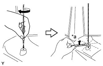 |
Install the radio antenna pole sub-assembly by hand until fully seated.
| *a | 1/8 turn (20 to 45 degrees) |
Using a 8 mm (5/16 inch) wrench, fully tighten the radio antenna pole about 1/8 turn (20 to 45 degrees) by turning it clockwise.
| 6. INSTALL FRONT FENDER MOULDING SUB-ASSEMBLY |
| 7. INSTALL FRONT BUMPER SIDE SUPPORT |
| 8. INSTALL FRONT FENDER MUDGUARD |
| 9. INSTALL ROCKER PANEL MOULDING |
| 10. INSTALL SIDE STEP SUB-ASSEMBLY (w/ Side Step) |
| 11. INSTALL FRONT BUMPER COVER |
Install the 4 clips.
Engage the 2 claws and install the front bumper cover.
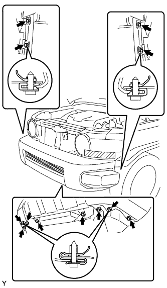 |
Install the 8 screws and the 4 bolts.
Install the 5 clips.
Remove the protective tape.
| 12. INSTALL RADIATOR GRILLE |
Engage the 5 clips and install the radiator grille.
Install the 2 screws.
Install the 2 clips.
| 13. INSTALL FRONT PILLAR GARNISH |
Engage the guide and the 2 clips and install the front pillar garnish.
| 14. INSTALL ASSIST GRIP ASSEMBLY |
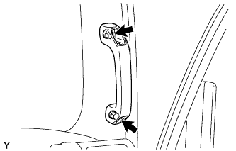 |
Install the assist grip with the 2 screws.
| 15. INSTALL ASSIST GRIP PLUG |
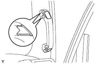 |
Engage the 2 claws and install the assist grip plug.
| 16. INSTALL FRONT DOOR OPENING TRIM WEATHERSTRIP |
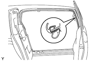 |
Install the front door opening trim weatherstrip.
| 17. INSTALL GLOVE COMPARTMENT DOOR ASSEMBLY |
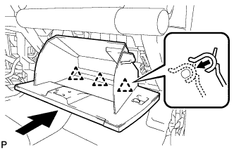 |
Install the glove compartment door assembly with the 3 hinges while holding it horizontal.
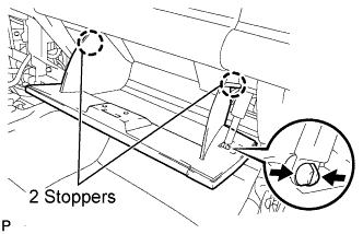 |
Slightly flex the upper part of the glove compartment door assembly, and install the glove compartment door assembly.
Install the glove compartment door stoppers onto the glove compartment door.
| 18. CONNECT CABLE TO NEGATIVE BATTERY TERMINAL |