 |
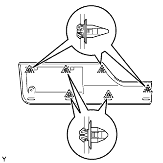
Install 6 new clips in the positions shown in the illustration.
- NOTICE:
- If you install the clips wrongly, the installation of the back door outside moulding RH will be improper.
SIDE MOULDING > INSTALLATION |
| 1. INSTALL BACK DOOR OUTSIDE MOULDING RH |
|
Install 6 new clips in the positions shown in the illustration.
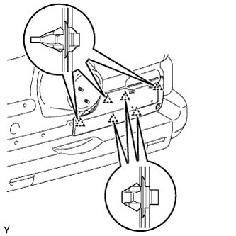 |
Engage the 6 clips and install the back door outside moulding RH.
Install the screw.
Remove the protective tape.
| 2. INSTALL BACK DOOR OUTSIDE MOULDING LH |
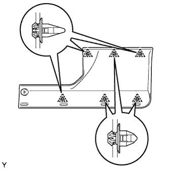 |
Install 6 new clips in the positions shown in the illustration.
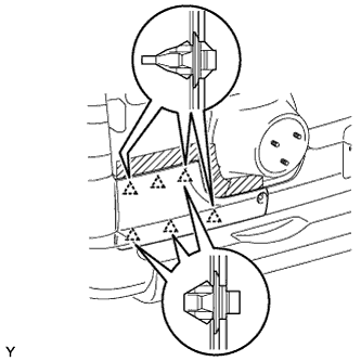 |
Engage the 6 clips and install the back door outside moulding LH.
Install the screw.
Remove the protective tape.
| 3. INSTALL SPARE TIRE |
| 4. INSTALL REAR DOOR OUTSIDE MOULDING SUB-ASSEMBLY |
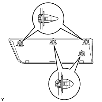 |
Install 4 new clips in the positions shown in the illustration.
Clean the attachment surface.
Using an infrared light, heat the double-sided tape remaining on the vehicle body.
| Item | Temperature |
| Vehicle Body | 40 to 60°C (104 to 140°F) |
Using a piece of cloth, rub the remaining double-sided tape off the vehicle body while it is hot from the infrared light.
Using a non-residue solvent, clean the attachment surface.
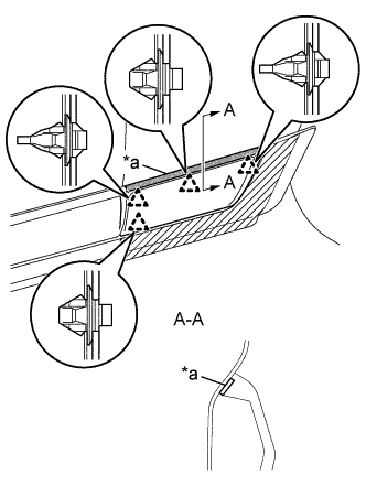 |
Remove the release paper from the face of the rear door outside moulding sub-assembly.
| *a | Double-sided Tape |
Engage the 4 clips and install the new rear door outside moulding sub-assembly.
Install the nut.
Remove the protective tape.
| 5. INSTALL FRONT DOOR OUTSIDE MOULDING SUB-ASSEMBLY |
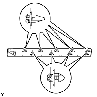 |
Install 9 new clips in the positions shown in the illustration.
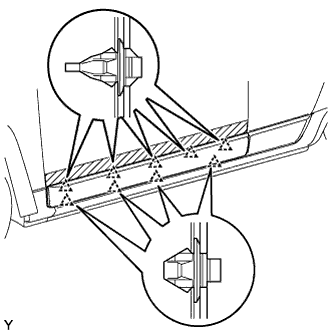 |
Engage the 9 clips and install the front door outside moulding sub-assembly.
Install the 2 nuts.
Remove the protective tape.
| 6. INSTALL NO. 1 QUARTER PANEL MOULDING PAD |
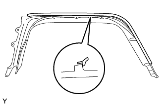 |
Install a new No. 1 quarter panel moulding pad in the position shown in the illustration.
| 7. INSTALL QUARTER OUTSIDE MOULDING SUB-ASSEMBLY |
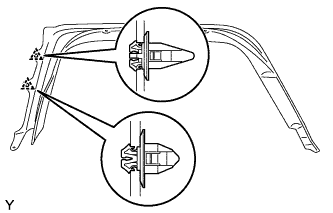 |
Install 2 new clips in the positions shown in the illustration.
Engage the 2 clips and install the quarter outside moulding sub-assembly.
Install the 8 screws
Install the clip.
Remove the protective tape.
| 8. INSTALL FRONT FENDER OUTSIDE MOULDING PAD |
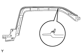 |
Install a new front fender outside moulding pad in the position shown in the illustration.
| 9. INSTALL FRONT FENDER MOULDING SUB-ASSEMBLY |
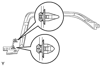 |
Install 2 new clips in the positions shown in the illustration.
Engage the 2 clips and install the front fender moulding sub-assembly.
Install the 5 screws.
Install the 2 clips
Remove the protective tape.
| 10. INSTALL ROCKER PANEL MOULDING |
Install 3 new clips in the positions shown in the illustration.
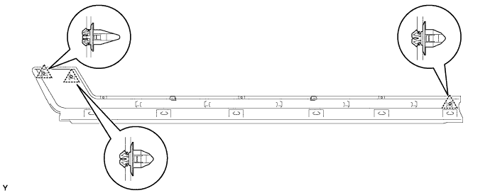
Engage the 3 clips, 2 claws and 5 guides and install the rocker panel moulding.
Install the 3 screws.
Install the 6 retainers.
| 11. INSTALL SIDE STEP SUB-ASSEMBLY (w/ Side Step) |
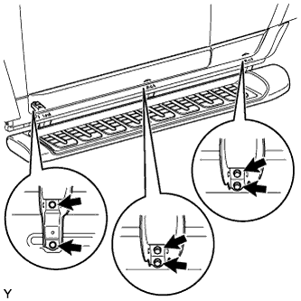 |
Install the step with 6 bolts.
| 12. INSTALL FRONT BUMPER SIDE SUPPORT |
Engage the 2 claws and install the front bumper side support LH.
Install the 2 screws.
| 13. INSTALL QUARTER PANEL MUDGUARD |
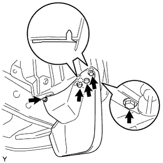 |
Align the 2 pins of the quarter panel mudguard with the installation hole of the quarter outside moulding.
Install the quarter panel mudguard with the 4 screws.
Install the clip.
| 14. INSTALL FRONT FENDER MUDGUARD |
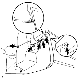 |
Align the pin of the front fender mudguard with the installation hole of the front fender moulding.
Install the front fender mudguard with the 5 screws.
Install the clip.
| 15. INSTALL REAR BUMPER COVER |
Engage the 6 claws and the 2 clips and install the rear bumper cover.
Connect the connector.
Connect the clamp and install the floor wire.
Tighten the 7 bolts and the 2 screws.
| 16. INSTALL FRONT BUMPER COVER |
Engage the 2 claws and install the front bumper cover.
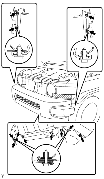 |
Install the 8 screws and the 4 bolts.
Install the 5 clips.
Remove the protective tape.
| 17. INSTALL RADIATOR GRILLE |
Engage the 5 clips and install the radiator grille.
Install the 2 screws.
Install the 2 clips.