Home › BODY › ENGINE HOOD / DOOR › BACK DOOR

BACK DOOR > REASSEMBLY

for Preparation Click here


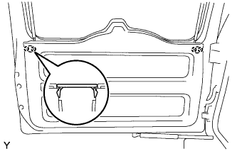
1. INSTALL HOLE PLUG
  1. Install the 2 hole plugs.


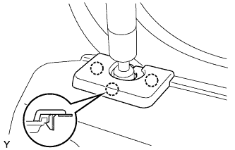
2. INSTALL CUSHION
  1. Install the 2 cushions.


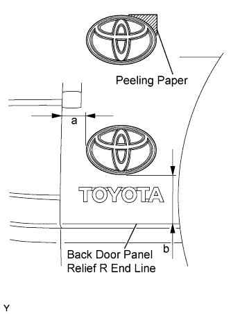
3. INSTALL REAR NAME PLATE


    B134748E01
  1. Clean the attachment surface.

    1. Using an infrared light, heat the double-sided adhesive tape remaining on the back door panel.

      HINT:
      Heat at 40 to 60°C (104 to 140°F) for 1 to 2 minutes.

    2. Using a shop rag or piece of cloth, rub the remaining double-sided adhesive tape off the back door panel while it is hot from the infrared light.

      NOTICE:
      Installing the rear name plate while any double-sided adhesive tape remains on the back door panel may cause adhesion failure. Therefore, completely remove the double-sided adhesive tape.

    3. Using a non-residue solvent, clean the attachment surface.
  1. Align the 2 pins and install a new rear name plate as shown in the illustration.

    Installation position:
    Mark
    Measurement (along surface)
    a
    49 mm (1.929 in.)
    b
    56.7 mm (2.232 in.)

    NOTICE:
    Install the rear name plate in an environment where the ambient temperature is over 20°C (68°F). If it is below 20°C (68°F), using an infrared light, heat the back door panel and the rear name plate up to 20 to 30°C (68 to 86°F) and install the rear name plate.


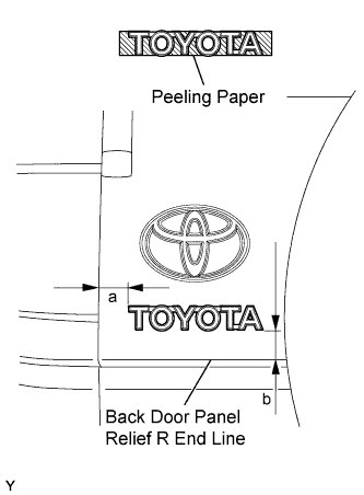
4. INSTALL NO. 2 BACK DOOR NAME PLATE


    B134745E01
  1. Clean the attachment surface.

    1. Using an infrared light, heat the double-sided adhesive tape remaining on the back door panel.

      HINT:
      Heat at 40 to 60°C (104 to 140°F) for 1 to 2 minutes.

    2. Using a shop rag or piece of cloth, rub the remaining double-sided adhesive tape off the back door panel while it is hot from the infrared light.

      NOTICE:
      Installing the No. 2 back door name plate while any double-sided adhesive tape remains on the back door panel may cause adhesion failure. Therefore, completely remove the double-sided adhesive tape.

    3. Using a non-residue solvent, clean the attachment surface.
  1. Install a new No. 2 back door name plate as shown in the illustration.

    Installation position:
    Mark
    Measurement (along surface)
    a
    37 mm (1.457 in.)
    b
    14.5 mm (0.571 in.)

    NOTICE:
    Install the back door name plate in an environment where the ambient temperature is over 20°C (68°F). If it is below 20°C (68°F), using an infrared light, heat the back door panel and the No. 2 back door name plate up to 20 to 30°C (68 to 86°F) and install the No. 2 back door name plate.


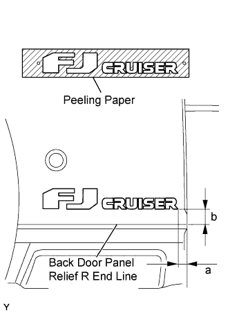
5. INSTALL NO. 1 BACK DOOR NAME PLATE


    B134742E01
  1. Clean the attachment surface.

    1. Using an infrared light, heat the double-sided adhesive tape remaining on the back door panel.

      HINT:
      Heat at 40 to 60°C (104 to 140°F) for 1 to 2 minutes.

    2. Using a shop rag or piece of cloth, rub the remaining double-sided adhesive tape off the back door panel while it is hot from the infrared light.

      NOTICE:
      Installing the No. 1 back door name plate while any double-sided adhesive tape remains on the back door panel may cause adhesion failure. Therefore, completely remove the double-sided adhesive tape.

    3. Using a non-residue solvent, clean the attachment surface.
  1. Install a new No. 1 back door name plate as shown in the illustration.

    Installation position:
    Mark
    Measurement (along surface)
    a
    28.4 mm (1.118 in.)
    b
    11.5 mm (0.453 in.)

    NOTICE:
    Install the No. 1 back door name plate in an environment where the ambient temperature is over 20 °C (68°F). If it is below 20°C (68°F), using an infrared light, heat the back door panel and the No. 1 back door name plate up to 20 to 30°C (68 to 86°F) and install the No. 1 back door name plate.
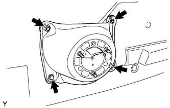


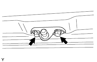
6. INSTALL BACK DOOR DAMPER STAY LOWER BRACKET
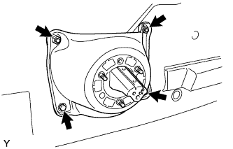

    B135999
  1. Install the back door damper stay lower bracket with the 2 bolts.

    Torque:
    20 N*m{ 199 kgf*cm , 14 ft.*lbf }


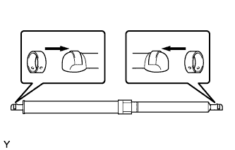
7. INSTALL BACK DOOR SUPPORT


B135599
  1. Install the 2 stop rings onto the back door support.

  1. Install the back door support.


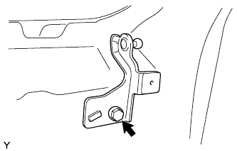
8. INSTALL BACK DOOR STAY UPPER BRACKET LH


    B135593
  1. Install the back door stay upper bracket with the bolt.

    Torque:
    7.0 N*m{ 71 kgf*cm , 62 in.*lbf }


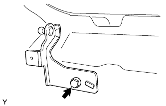
9. INSTALL BACK DOOR STAY UPPER BRACKET RH


    B135592
  1. Install the back door stay upper bracket with the bolt.

    Torque:
    7.0 N*m{ 71 kgf*cm , 62 in.*lbf }


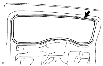
10. INSTALL NO. 2 BACK DOOR WEATHERSTRIP


    B135591
  1. Install the No. 2 back door weatherstrip.


11. INSTALL BACK DOOR HINGE ASSEMBLY RH


    B135998
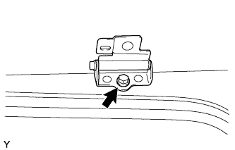
  1. Install the back door hinge with the bolt.

    Torque:
    20 N*m{ 199 kgf*cm , 14 ft.*lbf }


12. INSTALL BACK DOOR HINGE ASSEMBLY LH

HINT:
Use the same procedure as described for the RH side.


13. INSTALL BACK DOOR OUTSIDE HANDLE
  1. Install the bush.


    B139406
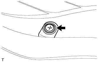
  1. Install the back door outside handle with the screw.


14. INSTALL BACK WINDOW LOCK STRIKER ASSEMBLY


B139405
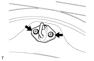
  1. Install the back window lock striker and retainer with the 2 screws.


15. INSTALL BACK WINDOW STAY UPPER BRACKET RH


B139404
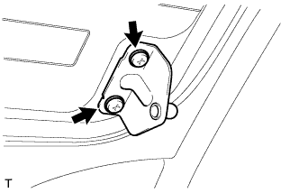
  1. Install the back window stay upper bracket and retainer with the 2 screws.


16. INSTALL BACK WINDOW STAY UPPER BRACKET LH

HINT:
Use the same procedure as described for the RH side.


17. INSTALL BACK DOOR GLASS


B139403
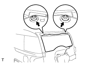
  1. Install the back door glass with the 2 nuts.

    Torque:
    5.5 N*m{ 56 kgf*cm , 49 in.*lbf }

  1. Connect the 2 connectors.


18. INSTALL BACK WINDOW SUPPORT LH


B135551
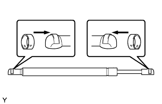
  1. Install the 2 stop rings onto the back window support.

  1. Install the back window support.


19. INSTALL BACK WINDOW SUPPORT RH

HINT:
Use the same procedure as described for the LH side.


20. INSTALL BACK DOOR SIDE FEMALE STOPPER SUB-ASSEMBLY


    B135549
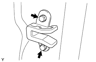
  1. Install the back door side female stopper with the 2 bolts.

    Torque:
    7.0 N*m{ 71 kgf*cm , 62 in.*lbf }


21. INSTALL HIGH MOUNTED STOP LIGHT ASSEMBLY


    B135165
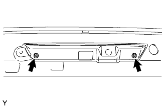
  1. Install the high mounted stop light with the 2 screws.


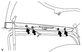
22. INSTALL REAR SPOILER


    B135163
  1. Install the rear spoiler with the 4 nuts.


    B135162
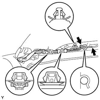
  1. w/ Rear Wiper:

    1. Connect the washer hose.

  1. Install the washer hose into the claw of the rear spoiler.

  1. Install the 3 clamps.

  1. Connect the high mounted stop light connector.


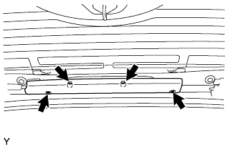
23. INSTALL NO. 1 REAR SPOILER COVER


    B135550
  1. Install the No. 1 rear spoiler cover with the 4 screws.


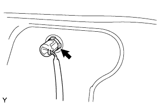
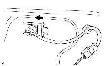
24. INSTALL BACK DOOR LOCK CYLINDER ASSEMBLY


    B135548
  1. Install the back door lock cylinder with the retainer.


    B135547
  1. Connect the connector and the 2 clamps.


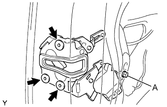
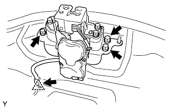
25. INSTALL BACK DOOR LOCK ASSEMBLY


    B135519E01
  1. Apply MP grease to the sliding and rotating areas of the back door lock.

  1. Using "Torx" socket wrench T30, install the back door lock with the 3 screws.

    Torque:
    5.0 N*m{ 51 kgf*cm , 44 in.*lbf }

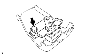
  1. Tighten bolt A.

    Torque:
    5.0 N*m{ 51 kgf*cm , 44 in.*lbf }

  1. Connect the connector.


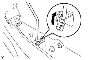
    B135518
  1. Connect the back door lock rod as shown in the illustration.


26. INSTALL BACK DOOR OUTSIDE GARNISH SUB-ASSEMBLY


    B135114
  1. Engage the 4 clips and install the back door outside garnish.


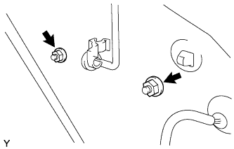
    B135111
  1. Tighten the 2 nuts.

    Torque:
    6.0 N*m{ 60 kgf*cm , 53 in.*lbf }


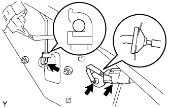
    B135110
  1. Connect the back door lock rod.

  1. Connect the license light connector.


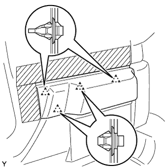
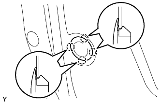
    B135109
  1. Engage the 4 claws and install the plug hole.


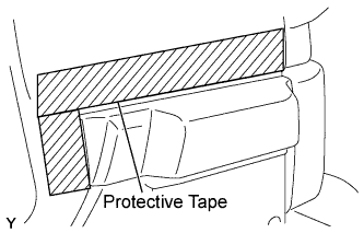
    B135112E01
  1. Remove the protective tape.


27. INSTALL BACK WINDOW LOCK ASSEMBLY


    B135521
  1. Install the back window lock with the 3 bolts.

    Torque:
    5.0 N*m{ 51 kgf*cm , 44 in.*lbf }

  1. Connect the connector and clamp.


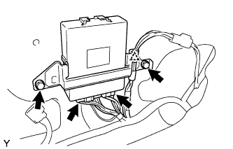
28. INSTALL MULTIPLEX NETWORK DOOR ECU


    B135545
  1. Install the multiplex network door ECU with the 2 screws.

  1. Connect the 3 connectors and 2 harness clamps.


29. INSTALL REAR WIPER MOTOR GROMMET (w/ Rear Wiper)


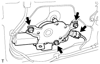
30. INSTALL REAR WIPER MOTOR (w/ Rear Wiper)


    E127890
  1. Install the rear wiper motor with the 3 bolts.

    Torque:
    5.5 N*m{ 56 kgf*cm , 49 in.*lbf }

  1. Connect the connector.


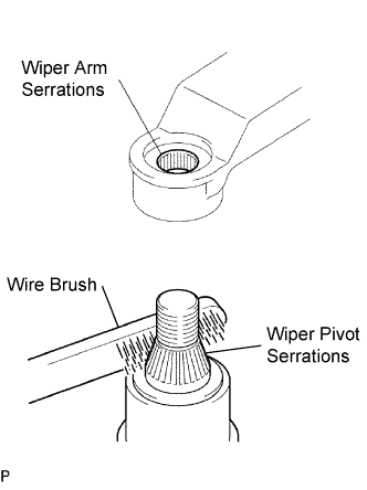
31. INSTALL REAR WIPER ARM AND BLADE ASSEMBLY (w/ Rear Wiper)


    E058837E10
  1. Scrape any metal powder off the serrated part of the wiper arm with a round file or the equivalent (when reinstalling).

  1. Clean the wiper pivot serrations with a wire brush.

  1. Operate the wiper, then stop the windshield wiper motor in the automatic stop position.


    E129609E01
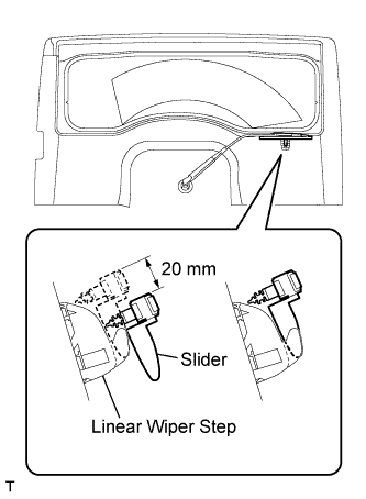
  1. Install the rear wiper arm in the position shown in the illustration with the nut.

    Torque:
    12 N*m{ 117 kgf*cm , 8 ft.*lbf }

    HINT:
    Using the nut, Tighten the rear wiper arm with the slider on the linear wiper step, 20 mm below the rise-up position in the rotational direction.

  1. Return the slider to the rise-up position.


    E129608
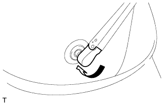
  1. Close the rear wiper arm head cap.


32. INSTALL BACK DOOR SERVICE HOLE COVER


    B135595
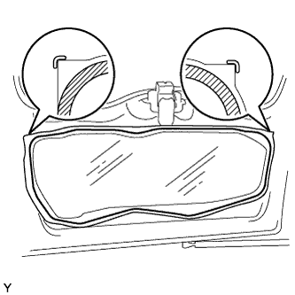
  1. Apply butyl tape to the door panel, then install the new back door service hole cover as shown in the illustration.

    HINT:
    1. When installing the service hole cover, pull the links and connectors out through the service hole.
    2. There should be no wrinkles or folds after attaching the service hole cover.
    3. After attaching the service hole cover, check the quality of the seal.


33. INSTALL BACK DOOR TRIM BOARD


    B135554
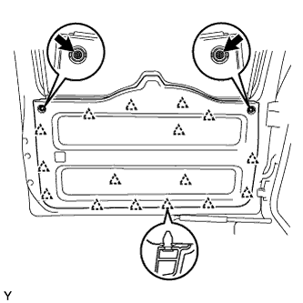
  1. Engage the 16 clips and install the back door trim board.

  1. Install the 2 screws.


34. INSTALL DOOR TRIM RETAINER CAP


    B135553
  1. Engage the 2 claws and install the door trim retainer cap.


35. INSTALL BACK DOOR TRIM COVER RH


B139382
  1. Engage the 3 claws and back door trim cover.


36. INSTALL BACK DOOR TRIM COVER LH

HINT:
Use the same procedure as described for the RH side.


37. INSTALL SPARE WHEEL CARRIER BRACKET SUB-ASSEMBLY
  1. Install the 4 spare wheel bracket pads.


    B135543
  1. Install the spare wheel carrier bracket with the 2 bolts and 2 nuts.

    Torque:
    48 N*m{ 489 kgf*cm , 35 ft.*lbf }


38. INSTALL SPARE WHEEL CARRIER BRACKET SUB-ASSEMBLY (w/ Rear Monitor)
  1. Install the 4 spare wheel bracket pads.


    B208355
  1. Install the spare wheel carrier bracket with the 2 bolts and 2 nuts.

    Torque:
    48 N*m{ 489 kgf*cm , 35 ft.*lbf }


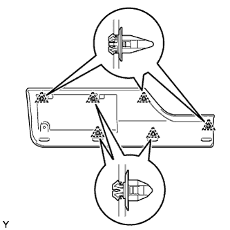
39. INSTALL BACK DOOR OUTSIDE MOULDING RH


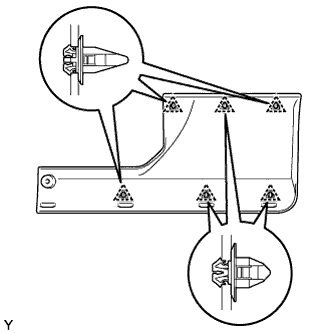
    B135032
  1. Install 6 new clips in the positions shown in the illustration.

    NOTICE:
    If you install the clips wrongly, the installation of the back door outside moulding RH will be improper.


    B135031
  1. Engage the 6 clips and install the back door outside moulding RH.

  1. Install the screw.

  1. Remove the protective tape.


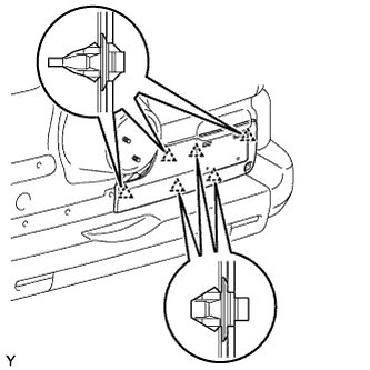
40. INSTALL BACK DOOR OUTSIDE MOULDING LH


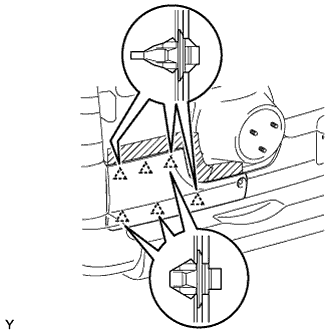
    B135028
  1. Install 6 new clips in the positions shown in the illustration.

    NOTICE:
    If you install the clips wrongly, the installation of the back door outside moulding LH will be improper.


    B135027
  1. Engage the 6 clips and install the back door outside moulding LH.

  1. Install the screw.

  1. Remove the protective tape.


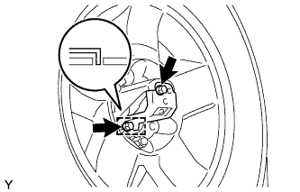
41. INSTALL SPARE DISC WHEEL

Torque:
88 N*m{ 897 kgf*cm , 65 ft.*lbf }


42. INSTALL REAR TELEVISION CAMERA ASSEMBLY (w/ Rear Monitor)


E172220
  1. Install the rear television camera with the bolt.

    Torque:
    32 N*m{ 326 kgf*cm , 24 ft.*lbf }


43. INSTALL SPARE WHEEL CARRIER NO. 2 BRACKET (w/ Rear Monitor)


B208354
  1. Connect the connector.

  1. Install the 2 bolts and install the spare wheel carrier No. 2 bracket.

    Torque:
    32 N*m{ 326 kgf*cm , 24 ft.*lbf }


44. INSTALL SPARE WHEEL COVER (w/ Rear Monitor)

Torque:
14 N*m{ 143 kgf*cm , 10 ft.*lbf }


45. INSTALL SPARE WHEEL NO. 2 COVER (w/ Rear Monitor)