 |
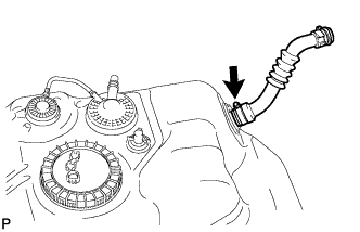
Connect a new fuel tank to filler pipe hose, as shown in the illustration, with the clamp.
FUEL TANK > INSTALLATION |
| 1. INSTALL FUEL TANK TO FILLER PIPE HOSE |
|
Connect a new fuel tank to filler pipe hose, as shown in the illustration, with the clamp.
| 2. INSTALL FUEL TANK BREATHER TUBE SUB-ASSEMBLY |
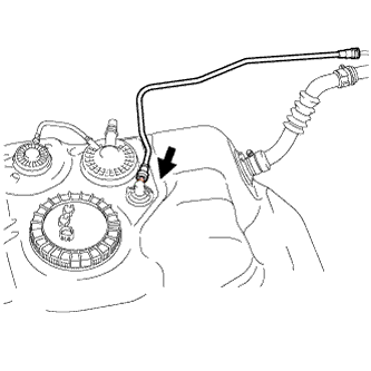 |
Push the tube connector into the pipe until the connector makes a "click" sound and install the retainer.
 | Push |
| 3. INSTALL FUEL SUCTION WITH PUMP AND GAUGE TUBE ASSEMBLY |
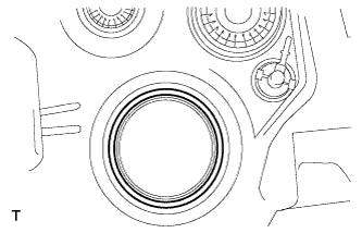 |
Install a new gasket onto the fuel tank.
Set the fuel suction tube assembly to the fuel tank.
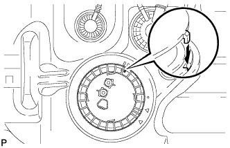 |
Fit the spline of the fuel suction tube assembly into the keyway of the fuel tank.
Install a new retainer.
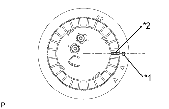 |
Align the mark on a new retainer with the rib on the fuel tank as shown in the illustration.
| *1 | Start Mark (Fuel Tank Side) |
| *2 | Start Mark (Retainer Side) |
Set the plate and claws of SST onto the fuel pump gauge retainer and temporarily tighten the bolts.
While firmly pressing the claws of SST against the ribs of the retainer, fully tighten each bolt.
Set SST handle in place.
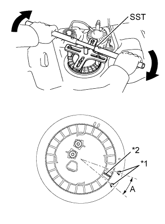 |
Using SST, turn the retainer 740° to 760° clockwise (more than 2 turns), and position the mark on the retainer within range A to install it.
| *1 | Fuel Tank Side Mark |
| *2 | Retainer Side Mark |
| 4. INSTALL FUEL TANK MAIN TUBE AND FUEL TANK RETURN TUBE |
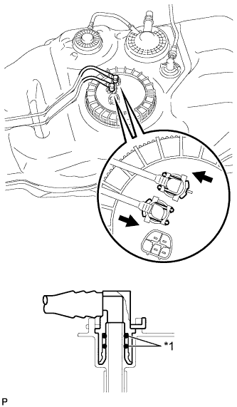 |
Install the fuel tank main tube and return tube with the 2 joint clips.
| *1 | O-Ring |
| Push |
| 5. INSTALL FUEL TANK CUSHION |
Install 4 new fuel tank cushions to the fuel tank.
| 6. INSTALL NO. 3 FUEL TANK PROTECTOR |
Install the No. 3 fuel tank protector with the 2 bolts and 3 claws.
| 7. INSTALL FUEL TANK ASSEMBLY |
Set a mission jack to the fuel tank.
Install the fuel tank and 2 fuel tank bands with the 2 clips, 2 pins and the 2 bolts.
| 8. INSTALL FUEL TANK VENT HOSE |
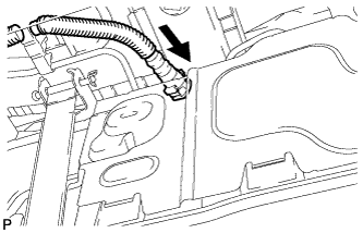 |
Connect the fuel tank vent hose.
| Push |
Align the fuel tank vent hose connector with the pipe, then push in the fuel tank vent connector until the retainer makes a "click" sound to connect the fuel tank vent hose to the charcoal canister.
| 9. CONNECT FUEL TANK MAIN TUBE AND FUEL TANK RETURN TUBE |
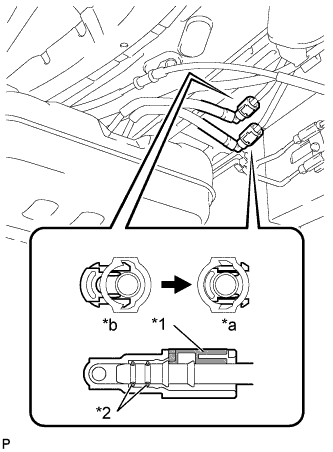 |
Push the tube connector into the pipe until the connector makes a "click" sound.
| *1 | Retainer |
| *2 | O-Ring |
| *a | Lock |
| *b | Unlock |
| 10. CONNECT FUEL TANK BREATHER TUBE SUB-ASSEMBLY |
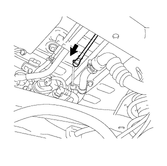 |
Push the tube connector into the pipe until the connector makes a "click" sound.
| Push |
| 11. CONNECT FUEL TANK TO FILLER PIPE HOSE |
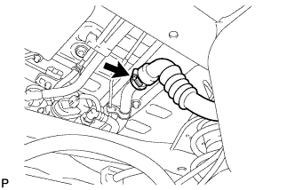 |
Connect the fuel tank to filler pipe hose, as shown in the illustration, with the clamp.
| 12. INSTALL NO. 1 FUEL TANK PROTECTOR SUB-ASSEMBLY (for Automatic Transmission) |
Install the fuel tank protector with the 4 nuts.
Install the fuel tank protector bracket with the 2 nuts.
| 13. INSTALL NO. 1 FUEL TANK PROTECTOR SUB-ASSEMBLY (for Manual Transmission) |
Install the fuel tank protector with the 4 nuts.
Install the fuel tank protector bracket with the nut.
| 14. INSTALL REAR FLOOR SERVICE HOLE COVER |
Connect the connector.
Install the 3 screws from the center floor.
Install the center floor silencer pad LH.
Install the floor carpet.
| 15. INSTALL REAR DOOR SCUFF PLATE LH |
Engage the 6 claws and install the rear door scuff plate.
| 16. INSTALL FRONT DOOR SCUFF PLATE LH |
Engage the 14 claws and install the front door scuff plate.
| 17. INSTALL REAR SEAT CUSHION ASSEMBLY LH |
Install the rear seat cushion assembly LH with the 2 bolts.
| 18. INSPECT FOR FUEL LEAK |
Connect the Techstream to the DLC3.
Turn the ignition switch to ON.
Turn the Techstream on.
Enter the following menus: Powertrain / Engine and ECT / Active Test / Control the Fuel Pump Speed / ON.
Check fuel pump operation.
Check for pressure in the fuel inlet tube from the fuel line. Check that the sound of fuel flowing in the fuel tank can be heard.
If there is no sound, check the integration relay, fuel pump, ECM and wiring connector.