FAN > INSTALLATION |
| 1. INSTALL FAN |
|
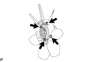
Install the fan onto the coupling with the 4 nuts.
| 2. INSTALL FAN SHROUD |
Install the fan pulley to the engine water pump assembly.
Place the fan shroud together with the fan and fluid coupling assembly between the radiator assembly and engine.
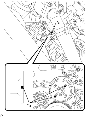 |
Align the paint marks of the same color (pink to pink and black to black) on the stud bolts of the engine water pump assembly and the outer flange of the fan and fluid coupling assembly, and assemble the parts.
| *a | Paint Mark |
Temporarily install the fan and fluid coupling assembly to the engine water pump assembly with the 4 nuts. Tighten the nuts as much as possible by hand.
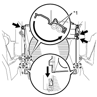 |
Engage the 2 guides of the fan shroud to the radiator assembly as shown in the illustration.
Install the fan shroud to the radiator assembly with the 2 bolts.
Install the radiator reserve tank assembly to the radiator assembly with the bolt.
Connect the 2 oil cooler hoses to the hose clamp and engage the clamp.
| *1 | Oil Cooler Hose |
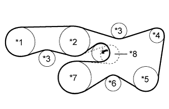 |
Set the fan and generator V belt onto every part.
| *1 | Vane Pump Assembly |
| *2 | Engine Water Pump Assembly |
| *3 | No. 2 Idler Pulley Sub-Assembly |
| *4 | Generator Assembly |
| *5 | Cooler Compressor Assembly |
| *6 | No. 1 Idler Pulley Sub-Assembly |
| *7 | Crankshaft Pulley |
| *8 | V-ribbed Belt Tensioner Assembly |
While turning the V-ribbed belt tensioner assembly counterclockwise, remove the pin.
Check that the belt fits properly in the ribbed grooves.
Tighten the 4 nuts of the fan and fluid coupling assembly.
Connect the radiator reserve tank hose to the radiator assembly.
| 3. INSTALL UPPER RADIATOR SUPPORT SEAL |
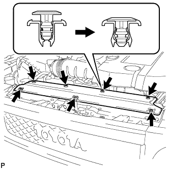 |
Engage the 7 clips and install the upper radiator support seal to the fan shroud.
| 4. INSTALL NO. 1 ENGINE UNDER COVER SUB-ASSEMBLY |
Hook the No. 1 engine under cover sub-assembly to the frame.
Install the 4 bolts to the No. 1 engine under cover sub-assembly.
| 5. INSTALL V-BANK COVER |
Engage the 2 hooks and install the V-bank cover to the No. 1 V-bank cover bracket.
Align the 2 V-bank cover grommets with the 2 pins and press down on the V-bank cover to engage the pins.