 |
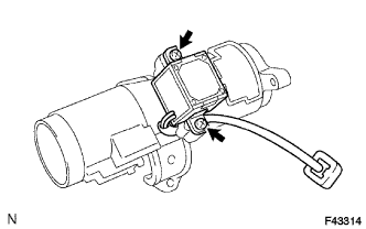
Install the key inter lock solenoid onto the steering column bracket assembly upper with the 2 screws.
STEERING COLUMN ASSEMBLY > REASSEMBLY |
| 1. INSTALL KEY INTER LOCK SOLENOID (for Automatic Transmission) |
|
Install the key inter lock solenoid onto the steering column bracket assembly upper with the 2 screws.
| 2. INSTALL IGNITION OR STARTER SWITCH ASSEMBLY |
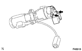 |
Install the ignition or starter switch assembly onto the steering column bracket assembly upper with the 2 screws.
| 3. INSTALL UN-LOCK WARNING SWITCH ASSEMBLY |
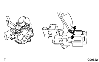 |
Install the un-lock warning switch assembly onto the steering column bracket assembly upper.
Connect the un-lock warning switch assembly connector to the ignition or starter switch assembly.
| 4. INSTALL IGNITION SWITCH LOCK CYLINDER ASSEMBLY |
Make sure that the ignition switch lock cylinder assembly is in the ACC position.
Install the ignition switch lock cylinder assembly.
| 5. INSTALL TRANSPONDER KEY AMPLIFIER |
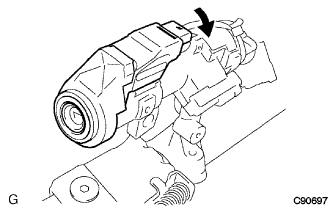 |
Align the transponder key amplifier with the installation position of the upper bracket with the amplifier inclined.
Push up the transponder key amplifier and connect it to the upper bracket.
| 6. INSTALL STEERING MAIN SHAFT ASSEMBLY |
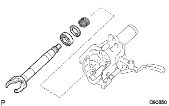 |
Install the compression spring, bearing thrust collar and bearing onto the No. 1 main shaft.
Temporarily install the steering column tube sub-assembly upper onto the No. 1 main shaft.
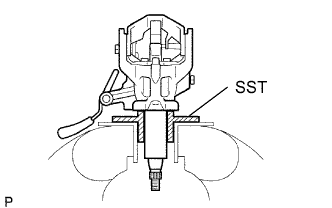 |
Secure the No. 1 main shaft with the steering column tube sub-assembly upper and SST in a vise.
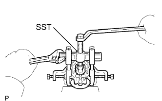 |
Using SST, compress the spring of the steering column tube sub-assembly upper.
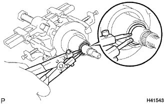 |
Using a snap ring expander, install a new snap ring onto the main shaft.
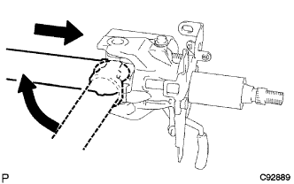 |
Assemble the No. 1 main shaft with the steering column tube sub-assembly upper and the No. 2 main shaft sub-assembly.
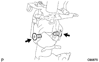 |
Using a 6 mm hexagon wrench, install the 2 tilt steering bolts.
Install the main shaft with the steering column tube sub-assembly upper onto the column tube.
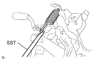 |
Using SST, install the tension spring.
Install the turn signal bracket with the 2 bolts.
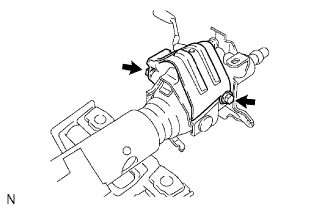 |
Install the steering column protector with the 2 bolts.
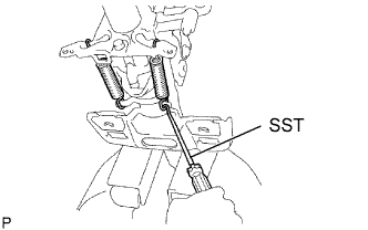 |
Using SST, install the 2 tension springs.
| 7. INSTALL STEERING COLUMN UPPER CLAMP |
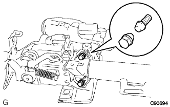 |
Temporarily install the steering column bracket assembly upper and steering column upper clamp with 2 new tapered-head bolts.
Tighten the 2 tapered-head bolts until the bolt heads break off.
| 8. INSTALL STEERING INTERMEDIATE SHAFT ASSEMBLY |
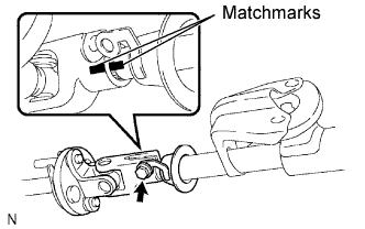 |
Align the matchmarks on the steering column assembly and the steering intermediate shaft assembly.
Install the steering intermediate shaft assembly and thrust stopper onto the steering column assembly with the bolt.