PROPELLER SHAFT ASSEMBLY > REASSEMBLY |
| 1. INSTALL REAR PROPELLER SHAFT UNIVERSAL JOINT SPIDER KIT |
|
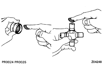
Apply MP grease to a new spider and spider bearings.
Fit the spider into the flange yoke.
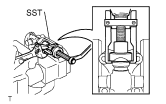 |
Using SST, install the spider bearings onto the spider.
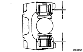
Using SST, adjust both bearings so that the snap ring grooves are at maximum and equal in width.
 |
Install 4 new snap rings of equal thickness which will allow no axial play.
| Parts No. | Thickness mm (in.) | Mark |
| 90520-25039 | 2.28 to 2.30 | 1 |
| 90520-25040 | 2.30 to 2.32 | 2 |
| 90520-25041 | 2.32 to 2.34 | - |
| 90520-25042 | 2.34 to 2.36 | Brown |
| 90520-25043 | 2.36 to 2.38 | Blue |
| 90520-25044 | 2.38 to 2.40 | 6 |
| 90520-25045 | 2.40 to 2.42 | 7 |
| 90520-25046 | 2.42 to 2.44 | 8 |
| 90520-25047 | 2.44 to 2.46 |  |
| 90520-25048 | 2.46 to 2.48 | 10 |
| 90520-25049 | 2.48 to 2.50 | A |
| 90520-25050 | 2.50 to 2.52 | B |
| 90520-25051 | 2.52 to 2.54 | C |
| 90520-25052 | 2.54 to 2.56 | D |
| 90520-25053 | 2.56 to 2.58 | E |
| 90520-25054 | 2.18 to 2.20 | J |
| 90520-25055 | 2.20 to 2.22 | K |
| 90520-25056 | 2.22 to 2.24 | F |
| 90520-25057 | 2.24 to 2.26 | G |
| 90520-25058 | 2.26 to 2.28 | H |
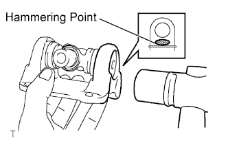 |
Using a hammer, tap the yoke until there is no clearance between the spider bearing outer race and snap ring.
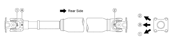
Align the matchmarks on the flange yoke and the sleeve yoke.
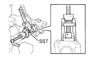 |
Using SST, install the spider bearings onto the spider.
Using SST, adjust both bearings so that the snap ring grooves are at maximum and equal in width.
Install 4 new snap rings of equal thickness which will allow no axial play.
| Parts No. | Thickness mm (in.) | Mark |
| 90520-25039 | 2.28 to 2.30 | 1 |
| 90520-25040 | 2.30 to 2.32 | 2 |
| 90520-25041 | 2.32 to 2.34 | - |
| 90520-25042 | 2.34 to 2.36 | Brown |
| 90520-25043 | 2.36 to 2.38 | Blue |
| 90520-25044 | 2.38 to 2.40 | 6 |
| 90520-25045 | 2.40 to 2.42 | 7 |
| 90520-25046 | 2.42 to 2.44 | 8 |
| 90520-25047 | 2.44 to 2.46 | |
| 90520-25048 | 2.46 to 2.48 | 10 |
| 90520-25049 | 2.48 to 2.50 | A |
| 90520-25050 | 2.50 to 2.52 | B |
| 90520-25051 | 2.52 to 2.54 | C |
| 90520-25052 | 2.54 to 2.56 | D |
| 90520-25053 | 2.56 to 2.58 | E |
| 90520-25054 | 2.18 to 2.20 | J |
| 90520-25055 | 2.20 to 2.22 | K |
| 90520-25056 | 2.22 to 2.24 | F |
| 90520-25057 | 2.24 to 2.26 | G |
| 90520-25058 | 2.26 to 2.28 | H |
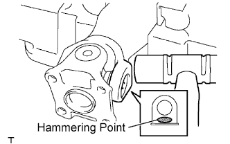 |
Using a plastic hammer, tap the yoke until there is no clearance between the spider bearing outer race and snap ring.
| 2. INSPECT UNIVERSAL JOINT SPIDER BEARING |
Check that the joints move smoothly.
Check the spider bearing axial play by turning the yoke while holding the shaft tightly.
| 3. INSPECT REAR PROPELLER SHAFT ASSEMBLY (for 4WD) |