 |
Remove screw <H>.
CLOCK > REMOVAL |
| 1. DISCONNECT CABLE FROM NEGATIVE BATTERY TERMINAL |
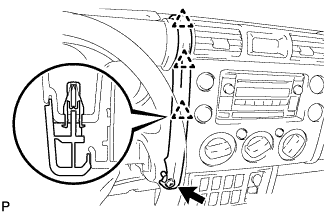
| 2. REMOVE INSTRUMENT PANEL GARNISH LH |
|
Remove screw <H>.
Disengage the 3 clips and remove the instrument panel garnish.
| 3. REMOVE INSTRUMENT PANEL GARNISH RH |
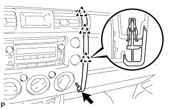 |
Remove screw <H>.
Disengage the 3 clips and remove the instrument panel garnish.
| 4. REMOVE INTEGRATION CONTROL PANEL ASSEMBLY |
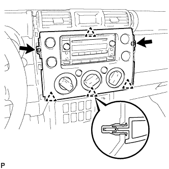 |
Remove the 2 <H> screws.
Disengage the 4 clips and remove the integration control panel assembly.
Disconnect the 3 connectors.
| 5. REMOVE RADIO RECEIVER ASSEMBLY |
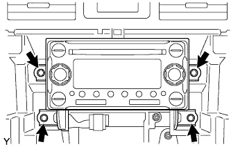 |
Remove the 4 bolts and the radio receiver.
Disconnect the connectors.
| 6. REMOVE CLOCK ASSEMBLY |
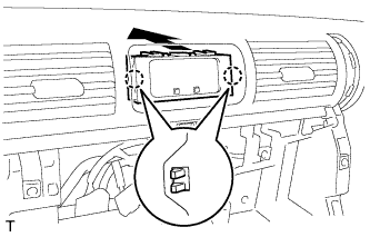 |
Disengage the 2 claws and remove the clock assembly.