 |
Check the resistance.
Using an ohmmeter, measure the resistance between the terminals.
- Standard resistance:
Tester Connection Condition Specified Condition 4 (ECU) - 6 (E) OFF Below 1 Ω 3 (IG) - 6 (E) ON Below 1 Ω 4 (ECU) - 6 (E) Below 1 Ω
BACK SONAR SWITCH ASSEMBLY > INSPECTION |
| 1. INSPECT BACK SONAR SWITCH ASSEMBLY |
|
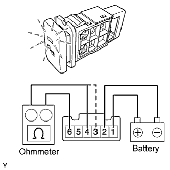
Check the resistance.
Using an ohmmeter, measure the resistance between the terminals.
| Tester Connection | Condition | Specified Condition |
| 4 (ECU) - 6 (E) | OFF | Below 1 Ω |
| 3 (IG) - 6 (E) | ON | Below 1 Ω |
| 4 (ECU) - 6 (E) | Below 1 Ω |
Check the operation.
Apply battery voltage to the terminals and check that the indicator illuminates.
| Condition | Standard |
| Positive battery - Terminal 1 (ILL+) Negative battery - Terminal 2 (ILL-) | Illuminates |
| 2. INSPECT BACK SONAR SWITCH BULB |
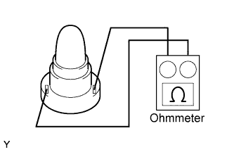 |
Check the resistance.
Using an ohmmeter, measure the resistance between the terminals.