 |
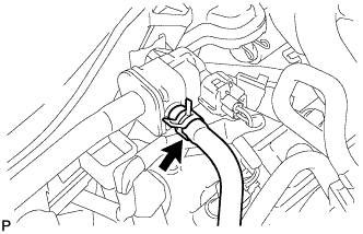
Disconnect the fuel vapor feed hose assembly from the purge VSV.
EMISSION CONTROL SYSTEM > ON-VEHICLE INSPECTION |
| 1. CHECK PURGE VSV |
Connect the Techstream to the DLC3.
Remove the V-bank cover .
|
Disconnect the fuel vapor feed hose assembly from the purge VSV.
Start the engine and turn the Techstream on.
Enter the following menus: Powertrain / Engine and ECT / Active Test / Activate the VSV for Evap Control.
Check that a vacuum occurs at the purge VSV port.
| Tester Operation | Specified Condition |
| EVAP VSV: OFF | Purge VSV has no suction |
| EVAP VSV: ON | Purge VSV has suction |
Exit the Active Test mode and connect the fuel vapor feed hose assembly to the purge VSV.
Enter the following menus: Powertrain / Engine and ECT / Data List / EVAP (Purge) VSV.
Warm up the engine and drive the vehicle.
Confirm that the purge VSV opens.
If the result is not as specified, replace the purge VSV, wire harness or ECM.
Install the V-bank cover .
| 2. INSPECT FUEL CUT-OFF RPM |
Start and warm up the engine.
Increase the engine speed to at least 3500 rpm.
Use a sound scope to check for injector assembly operation noise.
Check that when the accelerator pedal is released, injector assembly operation noise stops momentarily and then resumes.
If the result is not as specified, check the injector assembly, wiring and ECM.
| 3. VISUALLY INSPECT HOSES, CONNECTIONS AND GASKETS |
Check that there are no cracks, leaks or damage.
| 4. CHECK HOSES AND CONNECTORS |
Visually check for loose connections, sharp bends or damage.
| 5. CHECK FUEL TANK ASSEMBLY |
Visually check for deformation, cracks or fuel leakage.
| 6. INSPECT FUEL CUT OFF VALVE AND FILL CHECK VALVE |
Disconnect the fuel tank vent hose from the fuel tank assembly.
Connect the pressure gauge to the fuel cut off valve assembly.
Fill the fuel tank assembly with fuel.
Apply pressure at 4 kPa (0.04 kgf/cm2, 0.58 psi) to the vent port of the fuel tank assembly.
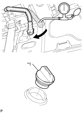 |
Remove the fuel tank cap assembly, and check that the pressure decreases.
| *1 | Fuel Tank Cap Assembly |
Reconnect the fuel tank vent hose to the fuel cut off valve assembly.
| 7. CHECK AIR INLET DUCT |
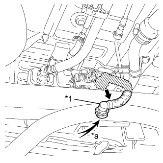 |
Disconnect the canister outlet hose from the charcoal canister sub-assembly.
| *1 | Canister Outlet Hose |
| *a | Air |
Check that air flows freely into the canister outlet hose.
If air does not flow freely into the canister outlet hose, repair or replace the canister outlet hose.
Reconnect the canister outlet hose to the charcoal canister sub-assembly.
| 8. INSPECT CANISTER PUMP MODULE (Pressure Sensor) |
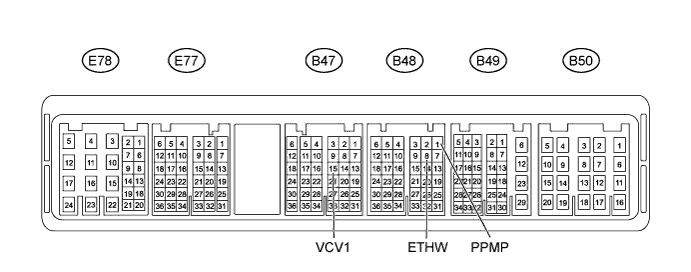
Check the power source voltage for pressure sensor.
Measure the voltage according to the value(s) in the table below.
| Tester Connection | Switch Condition | Specified Condition |
| B47-15 (VCV1) - B48-8 (ETHW) | Ignition switch ON | 4.5 to 5.0 V |
Check the output voltage of pressure sensor.
Remove the fuel tank cap assembly.
Measure the voltage according to the value(s) in the table below.
| Tester Connection | Switch Condition | Specified Condition |
| B48-1 (PPMP) - B48-8 (ETHW) | Ignition switch ON | 3.0 to 3.6 V |
Install the fuel tank cap assembly.
| 9. INSPECT SECONDARY AIR INJECTION SYSTEM OPERATION |
Start the engine and warm it up.
Turn the ignition switch off.
Connect the Techstream to the DLC3.
Turn the ignition switch to ON and turn the Techstream on.
Enter the following menus: Powertrain / Engine and ECT / Utility / Secondary Air injection check / (Manual Mode) / AIR PUMP: ON, ASV1: OPEN, ASV2: OPEN and AIR PUMP: OFF, ASV1: CLOSE, ASV2: CLOSE.
Start the engine.
Perform the AIR system intrusive operation while the engine is idling.
Check that the air pump (AIR PUMP), ASV and pressure in the AIR system passage (PRESSURE) status displayed on the Techstream indicate the conditions shown in the table below.
| Tester Operation | AIR PUMP | ASV | PRESSURE*1 | PULSATION*2 |
| AIR PUMP: ON, ASV: OPEN | ON | ON | 2.4 kPa or higher | 20 kPa or higher |
| AIR PUMP: OFF, ASV: CLOSE | OFF | OFF | Below 2.4 kPa | Below 30 kPa |
Turn the ignition switch off.