Home › ENGINE › 1GR-FE ENGINE CONTROL SYSTEM › HEATED OXYGEN SENSOR

HEATED OXYGEN SENSOR > INSTALLATION

for Preparation Click here


1. INSTALL HEATED OXYGEN SENSOR (for Bank 1 Sensor 2)


    A158663
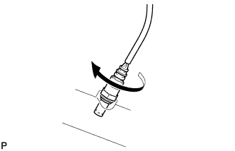
  1. Temporarily install the sensor to the exhaust pipe by hand.


    A229766E01
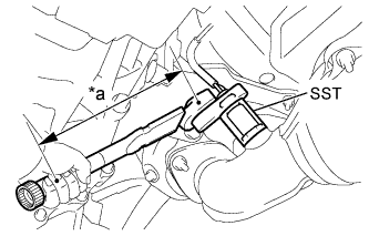
  1. Using SST, tighten the sensor.
    Text in Illustration 
    *a
    Fulcrum Length

    SST
    09224-00010  

    Torque:
    without SST:
    44 N*m{ 449 kgf*cm , 32 ft.*lbf }
    with SST:
    40 N*m{ 408 kgf*cm , 30 ft.*lbf }

    HINT:
    1. The "with SST" torque value is effective when using SST with a fulcrum length of 30 mm (1.18 in.).
    2. The "with SST" torque value is effective when using a torque wrench with a fulcrum length of 300 mm (11.81 in.) (Click here).
    3. This torque value is effective when SST is parallel to the torque wrench.
    4. Perform "Inspection After Repairs" after replacing the heated oxygen sensor (Click here).

  1. Connect the sensor connector.


2. INSTALL HEATED OXYGEN SENSOR (for Bank 2 Sensor 2)


    A158663
  1. Temporarily install the sensor to the exhaust pipe by hand.


    A223690E02
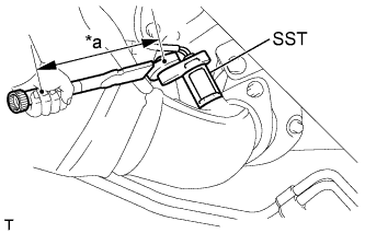
  1. Using SST, tighten the sensor.
    Text in Illustration 
    *a
    Fulcrum Length

    SST
    09224-00010  

    Torque:
    without SST:
    44 N*m{ 449 kgf*cm , 32 ft.*lbf }
    with SST:
    40 N*m{ 408 kgf*cm , 30 ft.*lbf }

    HINT:
    1. The "with SST" torque value is effective when using SST with a fulcrum length of 30 mm (1.18 in.).
    2. The "with SST" torque value is effective when using a torque wrench with a fulcrum length of 300 mm (11.81 in.) (Click here).
    3. This torque value is effective when SST is parallel to the torque wrench.
    4. Perform "Inspection After Repairs" after replacing the heated oxygen sensor (Click here).

  1. Connect the sensor connector.


3. INSPECT FOR EXHAUST GAS LEAK

HINT:
Perform "Inspection After Repairs" after repairing or replacing the exhaust system (Click here).