 |
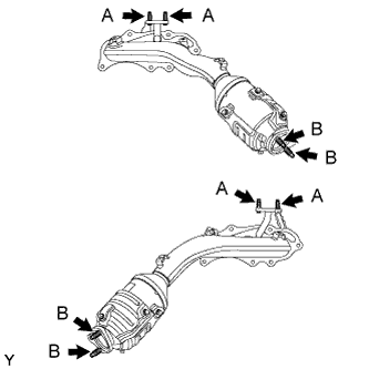
Using "Torx" socket wrench E6 and E10, install the 8 stud bolts to the exhaust manifold sub-assembly RH and LH.
- Torque:
- Stud bolt A:
- 5.0 N*m{ 51 kgf*cm , 44 in.*lbf }
- Stud bolt B:
- 20 N*m{ 204 kgf*cm , 15 ft.*lbf }
EXHAUST MANIFOLD > INSTALLATION |
| 1. INSTALL STUD BOLT (w/ Secondary Air Injection System) |
|
Using "Torx" socket wrench E6 and E10, install the 8 stud bolts to the exhaust manifold sub-assembly RH and LH.
| 2. INSTALL STUD BOLT (w/o Secondary Air Injection System) |
Using "Torx" socket wrench E10, install the 4 stud bolts to the exhaust manifold sub-assembly RH and LH.
| 3. INSTALL AIR FUEL RATIO SENSOR (for Bank 2 Sensor 1) |
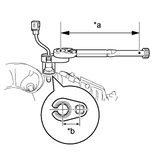 |
Using SST, install the air fuel ratio sensor to the exhaust manifold sub-assembly LH.
| *a | Fulcrum Length 300 mm (11.18 in.) |
| *b | Fulcrum Length 30 mm (1.18 in.) |
| 4. INSTALL EXHAUST MANIFOLD TO HEAD GASKET LH |
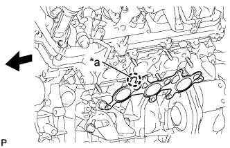 |
Install a new exhaust manifold to head gasket LH to the cylinder head sub-assembly.
| *a | Protrusion |
 | Front of Vehicle |
| 5. INSTALL EXHAUST MANIFOLD SUB-ASSEMBLY LH (w/ Secondary Air Injection System) |
Temporarily install the exhaust manifold sub-assembly LH to the cylinder head sub-assembly with the 6 new nuts.
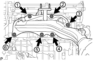 |
Install and uniformly tighten the 6 nuts in several steps in the sequence shown in the illustration.
Connect the air fuel ratio sensor connector.
| 6. INSTALL NO. 2 AIR TUBE (w/ Secondary Air Injection System) |
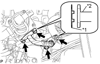 |
Install 2 new gaskets to the No. 2 air tube.
| *1 | New Gasket |
| *2 | No. 2 Air Tube |
Install the No. 2 air tube to the No. 2 emission control valve set and exhaust manifold sub-assembly LH with the 2 bolts and 2 nuts.
| 7. INSTALL EXHAUST MANIFOLD SUB-ASSEMBLY LH (w/o Secondary Air Injection System) |
Temporarily install the exhaust manifold sub-assembly LH to the cylinder head sub-assembly with the 6 new nuts.
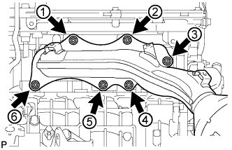 |
Install and uniformly tighten the 6 nuts in several steps in the sequence shown in the illustration.
Connect the air fuel ratio sensor connector.
| 8. INSTALL NO. 2 EXHAUST MANIFOLD HEAT INSULATOR |
Install the No. 2 exhaust manifold heat insulator to the exhaust manifold sub-assembly LH with the 3 bolts.
| 9. INSTALL NO. 2 MANIFOLD STAY |
Install the No. 2 manifold stay to the exhaust manifold sub-assembly LH with the 3 bolts.
| 10. INSTALL AIR FUEL RATIO SENSOR (for Bank 1 Sensor 1) |
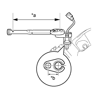 |
Using SST, install the air fuel ratio sensor to the exhaust manifold sub-assembly RH.
| *a | Fulcrum Length 300 mm (11.18 in.) |
| *b | Fulcrum Length 30 mm (1.18 in.) |
| 11. INSTALL EXHAUST MANIFOLD TO HEAD GASKET RH |
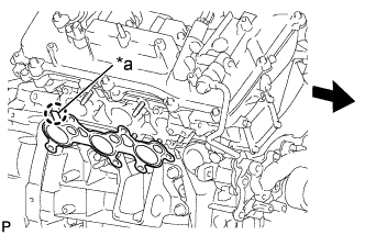 |
Install a new exhaust manifold to head gasket RH to the cylinder head sub-assembly.
| *a | Protrusion |
| Front of Vehicle |
| 12. INSTALL EXHAUST MANIFOLD SUB-ASSEMBLY RH (w/ Secondary Air Injection System) |
Temporarily install the exhaust manifold sub-assembly RH to the cylinder head sub-assembly with the 6 new nuts.
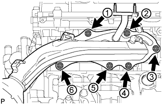 |
Install and uniformly tighten the 6 nuts in several steps in the sequence shown in the illustration.
Connect the air fuel ratio sensor connector.
| 13. INSTALL AIR TUBE (w/ Secondary Air Injection System) |
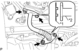 |
Install 2 new gaskets to the air tube.
| *1 | New Gasket |
| *2 | Air Tube |
Install the air tube to the emission control valve set and exhaust manifold sub-assembly RH with the 2 bolts and 2 nuts.
| 14. INSTALL EXHAUST MANIFOLD SUB-ASSEMBLY RH (w/o Secondary Air Injection System) |
Temporarily install the exhaust manifold sub-assembly RH to the cylinder head sub-assembly with the 6 new nuts.
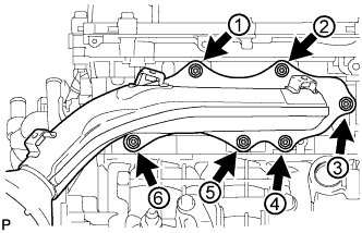 |
Install and uniformly tighten the 6 nuts in several steps in the sequence shown in the illustration.
Connect the air fuel ratio sensor connector.
| 15. INSTALL NO. 1 EXHAUST MANIFOLD HEAT INSULATOR |
Install the No. 1 exhaust manifold heat insulator to the exhaust manifold sub-assembly RH with the 3 bolts.
| 16. INSTALL MANIFOLD STAY |
Install the manifold stay to the exhaust manifold sub-assembly RH with the 3 bolts.
| 17. INSTALL FRONT EXHAUST PIPE ASSEMBLY |
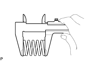 |
Using vernier calipers, measure the free length of the compression spring.
By hand, insert a new gasket into the rear flange of the front exhaust pipe assembly.
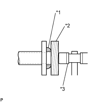 |
Using a plastic-faced hammer, place a wooden block against the gasket and gradually tap in the gasket all the way to the edge of the front exhaust pipe assembly flange.
| *1 | Gasket |
| *2 | Wooden Block |
| *3 | Plastic-faced Hammer |
Install a new gasket to the front flange of the front exhaust pipe assembly.
Install the front exhaust pipe assembly to the exhaust manifold sub-assembly RH with 2 new nuts.
Connect the front exhaust pipe assembly to the center exhaust pipe assembly with the 2 bolts and the 2 compression springs.
Connect the heated oxygen sensor connector.
| 18. INSTALL FRONT NO. 2 EXHAUST PIPE ASSEMBLY |
Install the 2 new gaskets to the front No. 2 exhaust pipe assembly.
Connect the exhaust pipe support and install the front No. 2 exhaust pipe assembly.
Connect the front No. 2 exhaust pipe assembly to the exhaust manifold sub-assembly LH with 2 new nuts.
Connect the front No. 2 exhaust pipe assembly to the front exhaust pipe assembly with the 2 bolts.
Connect the heated oxygen sensor connector.
| 19. INSTALL EXHAUST PIPE STOPPER BRACKET (for 4WD) |
Install the exhaust pipe stopper bracket to the frame sub-assembly with the 2 bolts.
| 20. INSTALL AIR CLEANER CASE SUB-ASSEMBLY |
Install the air cleaner case sub-assembly with the 3 bolts.
| 21. INSTALL AIR CLEANER FILTER ELEMENT SUB-ASSEMBLY |
Install the air cleaner filter element sub-assembly to the air cleaner case sub-assembly.
| 22. INSTALL AIR CLEANER CAP SUB-ASSEMBLY AND AIR CLEANER HOSE ASSEMBLY |
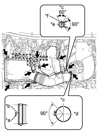 |
Install the air cleaner cap with the 4 hinges.
Install the No. 1 air cleaner hose with the clamp.
| *a | Protrusion |
| *b | Groove |
| *c | Top |
| *d | Front |
| *e | RH |
| *f | Paint mark of the hose |
Install the bolt.
Connect the ventilation hose and vacuum hose.
Engage the 4 wire harness clamps.
Connect the MAF meter connector.
| 23. INSTALL V-BANK COVER |
Engage the 2 hooks and install the V-bank cover to the No. 1 V-bank cover bracket.
Align the 2 V-bank cover grommets with the 2 pins and press down on the V-bank cover to engage the pins.
| 24. INSPECT FOR EXHAUST GAS LEAK |
| 25. INSTALL FRONT FENDER REAR SPLASH SHIELD RH |
Install the front fender rear splash shield RH to the front fender apron sub-assembly RH with the 5 clips.
| 26. INSTALL FRONT FENDER APRON SEAL RH |
Install the front fender apron seal RH to the front fender apron sub-assembly RH with the 4 clips.
| 27. INSTALL FRONT FENDER REAR SPLASH SHIELD LH |
Install the front fender rear splash shield LH to the front fender apron sub-assembly LH with the 5 clips.
| 28. INSTALL FRONT FENDER APRON SEAL LH |
Install the front fender apron seal LH to the front fender apron sub-assembly LH with the 5 clips.