Home › ENGINE › 1GR-FE EMISSION CONTROL › AIR SWITCHING VALVE (for Bank 1)

AIR SWITCHING VALVE (for Bank 1) > INSTALLATION

for Preparation Click here


1. INSTALL EMISSION CONTROL VALVE SET
  1. Install the emission control valve set to the cylinder head cover sub-assembly with the 3 nuts.

    Torque:
    21 N*m{ 214 kgf*cm , 15 ft.*lbf }


    A288092E01
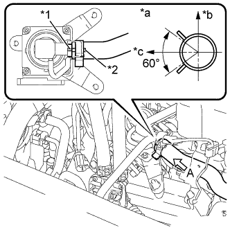
  1. Connect the air hose assembly to the emission control valve set with the hose clamp as shown in the illustration.
    Text in Illustration 
    *1
    Protrusion of Emission Control Valve Set
    *2
    Paint Mark of No. 1 Air Injection System Hose
    *a
    View A
    *b
    Upper of Vehicle
    *c
    RH Side of Vehicle

    HINT:
    Make sure the direction of the hose clamp is as shown in the illustration.
  1. Connect the emission control valve set connector.


2. INSTALL AIR TUBE


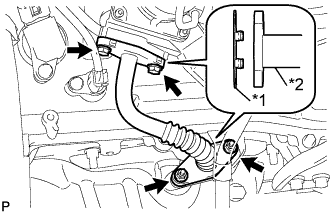
    A226791E03
  1. Install 2 new gaskets to the air tube.
    Text in Illustration 
    *1
    New Gasket
    *2
    Air Tube

  1. Install the air tube to the emission control valve set and exhaust manifold sub-assembly RH with the 2 bolts and 2 nuts.

    Torque:
    10 N*m{ 102 kgf*cm , 7 ft.*lbf }


3. INSTALL AIR CLEANER CASE SUB-ASSEMBLY
  1. Install the air cleaner case sub-assembly to the engine room compartment with the 3 bolts.

    Torque:
    12 N*m{ 122 kgf*cm , 9 ft.*lbf }

  1. Engage the wire harness clamp and install the wire harness to the air cleaner case sub-assembly.

  1. Install the air cleaner filter element to the air cleaner case sub-assembly.


4. INSTALL AIR CLEANER CAP SUB-ASSEMBLY WITH AIR CLEANER HOSE ASSEMBLY


    A227195E01
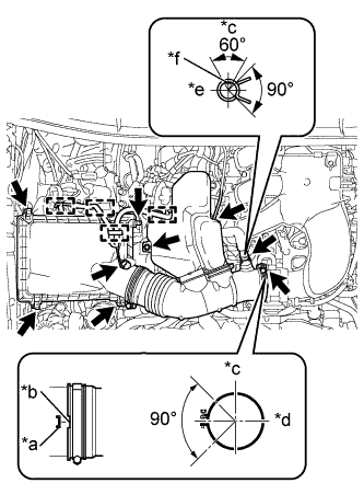
  1. Install the air cleaner cap with the 4 hinges.

  1. Install the No. 1 air cleaner hose with the clamp.

    Torque:
    5.0 N*m{ 51 kgf*cm , 44 in.*lbf }

    Text in Illustration 
    *a
    Protrusion
    *b
    Groove
    *c
    Top
    *d
    Front
    *e
    RH
    *f
    Paint mark of the hose

  1. Install the bolt.

    Torque:
    5.0 N*m{ 51 kgf*cm , 44 in.*lbf }

  1. Connect the ventilation hose and vacuum hose.

    HINT:
    The direction of the hose clamp is indicated in the illustration.

  1. Engage the 4 wire harness clamps.

  1. Connect the MAF meter connector.


5. INSTALL V-BANK COVER
  1. Engage the 2 hooks and install the V-bank cover to the No. 1 V-bank cover bracket.

  1. Align the 2 V-bank cover grommets with the 2 pins and press down on the V-bank cover to engage the pins.