Home › ENGINE › 1GR-FE EMISSION CONTROL › AIR SWITCHING VALVE (for Bank 1)

AIR SWITCHING VALVE (for Bank 1) > INSPECTION

for Preparation Click here


1. INSPECT EMISSION CONTROL VALVE SET


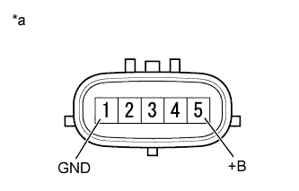
    A188033E01
  1. Measure the resistance according to the value(s) in the table below.
    Text in Illustration 
    *a
    Component without harness connected
    (Emission Control Valve Set)

    Standard Resistance:
    Tester Connection
    Condition
    Specified Condition
    1 (GND) - 5 (+B)
    20°C (68°F)
    4.5 to 5.5 Ω
    1 (GND) - Body ground
    Always
    1 MΩ or higher
    5 (+B) - Body ground

    NOTICE:
    When measuring the resistance, do not touch terminals 2, 3 or 4.

    HINT:
    1. When measuring the resistance make sure that the surface temperature of the emission control valve set is 20°C.
    2. If the result is not as specified, replace the emission control valve set.


    A224403E03
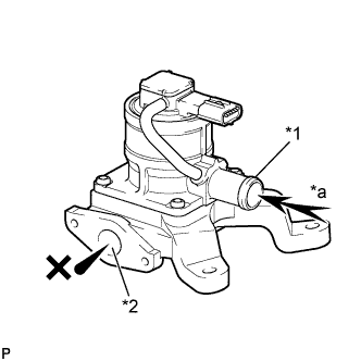
  1. Check the operation of the emission control valve set.

    1. Check that air does not flow from port A to port B.
      Text in Illustration 
      *1
      Port A
      *2
      Port B
      *a
      Air

      NOTICE:
      Make sure the applied pressure is 30 kPa (0.3 kgf/cm2, 4.4 psi) or less.

      If the result is not as specified, replace the emission control valve set.
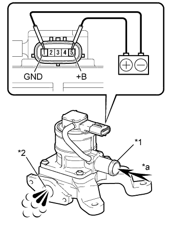


    2. A288094E01
    3. Apply battery voltage between the terminals of the emission control valve set.

      NOTICE:
      When applying voltage, do not touch terminals 2, 3 or 4.

    4. Check that air flows from port A to port B.
      Text in Illustration 
      *1
      Port A
      *2
      Port B
      *a
      Air

      OK:
      Condition
      Specified Condition
      Battery Positive (+) → 5 (+B)
      Battery Negative (-) → 1 (GND)
      Air Flows Out

      If the result is not as specified, replace the emission control valve set.