 |
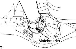
Put matchmarks on both flanges.
PROPELLER SHAFT ASSEMBLY (for Long Wheelbase) > REMOVAL |
| 1. REMOVE PROPELLER SHAFT ASSEMBLY |
|
Put matchmarks on both flanges.
Remove the 4 nuts, bolts and washers.
Remove the propeller shaft assembly.
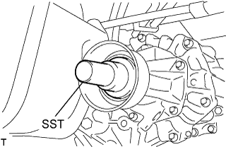 |
Insert SST in the transmission to prevent oil leakage.
Use the following SST for the automatic transmission
Use the following SST for the manual transmission
| 2. INSPECT PROPELLER SHAFT ASSEMBLY |
Visually check the propeller shaft assembly.
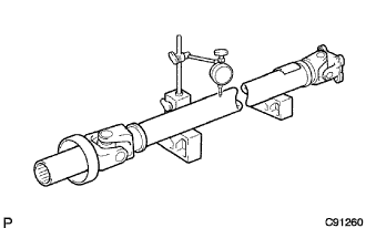 |
Using a dial indicator, inspect the runout of the shaft tube.
| Shaft tube length mm (in.) | Maximum runout mm (in.) |
| 800 (31.496) or more | 0.4 (0.0157) |
| Less than 800 (31.496) | 0.3 (0.0118) |
| 3. INSPECT UNIVERSAL JOINT SPIDER ASSEMBLY |
Check that the spider bearing rotates smoothly.
Check that there is no play in the spider bearing.
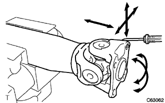 |
Using a spring tension gauge, hang the hook of the spring tension gauge on the bolt hole of the flange yoke and measure the rotating force.