 |
Pass the control cable assembly through the floor hole.
SHIFT AND SELECT TRANSMISSION CONTROL CABLE > INSTALLATION |
| 1. CONNECT TRANSMISSION CONTROL CABLE ASSEMBLY |
|
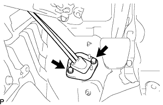
Pass the control cable assembly through the floor hole.
Install the transmission control cable assembly with the 2 bolts.
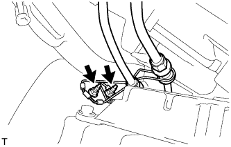 |
Wide body LHD steering position type:
Install the control cable bracket No.3 to the transmission control cable assembly.
Install the control cable bracket No.3 with the 2 nuts.
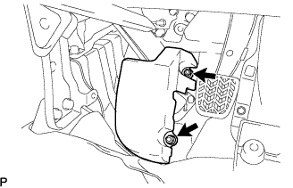 |
Install the front floor footrest with the 2 nuts.
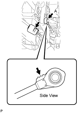 |
Install the transmission control cable assembly to the shift lever.
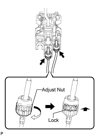 |
Turn the control cable assembly adjust nut clockwise 180°. While holding the adjust nut, push in the locks.
Install the control cable assembly to the shift lever.
| 2. INSTALL TRANSMISSION CONTROL CABLE ASSEMBLY |
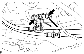 |
Install the control cable bracket No.2 to the transmission control cable assembly.
Install the control cable bracket No.2 with the 2 nuts.
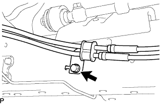 |
Install the clamp with the bolt.
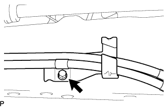 |
Install the control cable support to the control cable assembly.
Install the control cable support with the bolt.
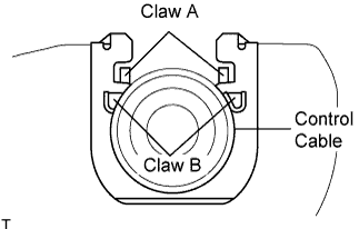 |
Install new 2 clips to the control cable bracket No.1.
Install the transmission control cable assembly to the control cable bracket No.1.
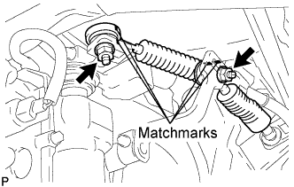 |
Align the matchmarks on the control cable assembly and the outer lever.
Install the transmission control cable assembly to the outer lever with the 2 nuts.
| 3. INSTALL INSTRUMENT PANEL FINISH PANEL LOWER CENTER |
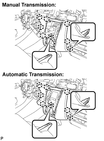 |
Engage the 8 claws and install the instrument panel finish panel lower center.
| 4. INSTALL SHIFTING HOLE COVER ASSEMBLY |
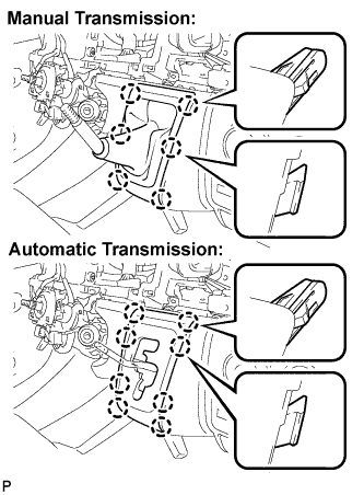 |
Manual Transmission:
Engage the 6 claws and install the shifting hole cover assembly.
Automatic Transmission:
Engage the 8 claws and install the sifting hole cover assembly.
| 5. INSTALL SHIFT LEVER KNOB |
| 6. INSTALL PARKING BRAKE HOLE COVER |
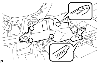 |
Engage the 6 claws and install the parking brake hole cover.
| 7. INSTALL INSTRUMENT PANEL UNDER COVER SUB-ASSEMBLY NO.1 |
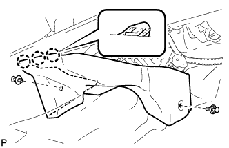 |
Engage the 3 claws.
Install the instrument panel No.1 under cover sub-assembly with the 2 clips.
| 8. INSTALL INSTRUMENT PANEL FINISH PANEL LOWER |
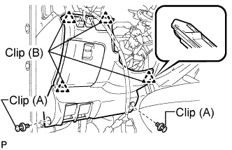 |
Engage the 4 clips (B).
Install the instrument panel finish panel lower with the 2 clips (A).
| 9. CONNECT CABLE TO NEGATIVE BATTERY TERMINAL |
| 10. PERFORM INITIALIZATION |